Thursday, October 23, 2014
Making a Solar Energy Powered an iPhone Battery Charger
For faster charging, a larger solar cell can be attached to the bag. Enough power can be generated to fully charge an iPhone in about 5.5 hours and an iPod Touch in 4 hours using a slightly larger solar cell with 6V at 250mAh. The charger will automatically switch to trickle charging when the cell reaches full charge. The charging current is limited to 100mA when charging using the mini USB port and the charging is limited to 280mA when charging using the barrel plug jack

.
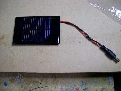
The materials needed to build the charger include a small solar cell, Lithium Polymer battery charger, minty boost kit, adhesive backed Velcro, Altoids tin, connector/wire, and small double adhesive squares as shown in the images below. An input power that ranges from 3.7V to 7V maximum can be accepted by the single cell Lithium Polymer. In bright sunlight, the solar cell maxes out at approximately 5V at 100mA. A larger solar cell with 6V at 250mA can be used for faster charging.

The images below show the assembly of minty boost kit where a JST connector is soldered to the minty boost PCB instead of connecting the battery holder in the kit. The minty boost circuit is allowed to connect to the Lithium Polymer battery charger circuit with this tiny connector. The minty boost is tested by connecting the battery pack and the charger circuit, the Lithium Polymer battery connects to the connector marked GND on the charger board and the minty boost connects to the connector marked SYS.

To fit the charger, a notch is cut out of the other side of the Altoids tin and used double sided adhesive to secure the charging circuit to the bottom of the Altoids as shown below. The bottom of either one of the circuit boards should not touch the bottom of the Altoids tin while reconnecting the minty boost PCB and the battery to the charging circuit.

Connecting or adding the solar cell can be done in different ways. Shortening the connector leads and plugging the barrel plug into the barrel jack on the charging circuit is one way. The other method is using another JST connector to replace the connector and plugging it into the third connector marked 5V on the charging circuit. Since there is no bog barrel plug sticking out of the side of the tin, using the second method is cleaner.
As shown in the photos below, some 2” Velcro was used to attach the solar cell to the top of the Altoids. To help protect the battery, a layer of clear packing tape was used for wrapping. N top of the two circuit boards, the battery pack is then set down. A red LED on the charger board will light up when the Mighty Minty Boost is set out in the bright sun. The iPod/iPhone/USB powered device can be connected once it is fully charged.

Monday, October 20, 2014
24V DC Powered Beeper with 4 Separate Inputs

Wednesday, September 17, 2014
USB powered battery charger circuit
Piezo Powered Lamp Circuit Schematics
Energy is becoming ever more expensive, and some fresh ideas are needed. There are already human-powered devices on the market, most of which employ a dynamo to generate power. It is also possible to recover energy from a piezo crystal of the sort found, for example, in the loudspeakers in greetings cards. Making use of this device is relatively straightforward.
Piezo-Powered Lamp Circuit Diagram :

Piezo crystals can generate voltages of many tens of volts when given a firm enough prod with a finger to bend the baseplate. The charge moved, however, is relatively small and the crystal is effectively a capacitor with a capacitance of only around 20 nF to 50 nF. This means that we need larger-scale storage in the form of an electrolytic capacitor.
The piezo crystal can be treated as an alternating current source. We therefore need a rectifier and a reservoir capacitor. Pressing the metal surface of the transducer ten or twenty times with a finger will charge the electrolytic in steps to the point where it has enough charge to drive a LED. The circuit is a ‘charge pump’ in the full sense of the term.
When the button is pressed the electrolytic discharges into the LED, which emits a brief, but bright, flash of light.
Author : Burkhard Kainka - Copyright : Elektor
Monday, September 15, 2014
Battery powered Night Lamp Circuit
Ultra-low current drawing 1.5V battery supply
An optional Photo resistor will switch-off the schema in daylight or when room lamps illuminate, allowing further current economy.
This device will run for about 3 months continuously on an ordinary AA sized cell or for around 6 months on an alkaline type cell but, adding the Photo resistor schemary, running time will be doubled or, very likely, triplicated.

R1,R2___________1M 1/4W Resistors
R3_____________47K 1/4W Resistor (optional: see Notes)
R4____________Photo resistor (any type, optional: see Notes)

C1____________100nF 63V Polyester Capacitor
C2____________220µF 25V Electrolytic Capacitor

D1______________LED Red 10mm. Ultra-bright (see Notes)
D2___________1N5819 40V 1A Schottky-barrier Diode (see Notes)

IC1____________7555 or TS555CN CMos Timer IC

B1_____________1.5V Battery (AA or AAA cell etc.)
- IC1 must be a CMos type: only these devices can safely operate at 1.5V supply or less.
- If you are not needing Photo resistor operation, omit R3 & R4 and connect pin 4 of IC1 to positive supply.
- Ordinary LEDs can be used, but light intensity will be poor.
- An ordinary 1N4148 type diode can be used instead of the 1N5819 Schottky-barrier type diode, but LED intensity will be reduced due to the higher voltage drop.
- Any Schottky-barrier type diode can be used in place of the 1N5819, e.g. the BAT46, rated @ 100V 150mA.