Thursday, October 23, 2014
Browse »
home »
40m
»
80m
»
circuit
»
diagram
»
or
»
receiver
»
regenerative
»
simple
»
Simple Regenerative Receiver Circuit Diagram 80m or 40m

Simple Regenerative Receiver Circuit Diagram 80m or 40m
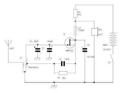
This is a simple design, can have excellent results, he is a recipient of regeneration, if you have never built any receiver, this is one you will build Easy. The circuit described is simple and has many limitations in sensitivity and selectivity, but is able to receive signals from radio amateurs (40m or 80m) in SSB and CW, and as output using a small headset crystal.
He will have a saturation if there are strong stations available on AM broadcast band of 41m at night.L1 is a small toroid T50-2 (red) with about 18 to 20 times (40m) or 35 to 40 times (80m) in the main winding connected to the FET with a single coupling circuit facing the antenna connection.
The center tap is about 20% of the primary winding. C1 is adjusted to set the radio band to the 40m and C2 then acts as a fine tuning within the band.The supply of 12 to 14V, R2 should be increased 5K6 or 6K8 output will be higher and similar sensitivity to-100dBm (about 2uV).
Regenerative Receiver Circuit Diagram

Subscribe to:
Post Comments (Atom)
No comments:
Post a Comment