Showing posts with label simple. Show all posts

Saturday, October 25, 2014

Simple Indicator for Dynamic Limiter Schematic Diagram

The indicator described here is specifically designed for adjusting the dynamic limiter described elsewhere in this edition and checking whether the maximum level of the reference voltage (P1) needs to be modified. Her e we use a 4 -to -16 decoder IC (type 4514) to monitor the state of the four-bit up/down counter in the limiter circuit. This IC can be powered from the ±8 V supply voltages of the limiter. The limiter board has a 6-way connector (K5) that provides access to the four counter outputs and the sup-ply voltages. Connector K1 of the indicator circuit can be connected to K5 on the limiter board.
 Indicator for Dynamic Limiter Schematic

One output of the 4514 goes high for each unique 4-bit combination on its inputs, while the other outputs remain logic Low. A separate current-limiting resistor is connected in series with each LED. It was not possible to use a common cathode resistor here because most LEDs have a maximum reverse blocking voltage of only 5 V, while the supply voltage here (16 V) is a good deal higher.

The 16 LEDs ar ranged in a r ow pr ov ide a ‘fluid’ indication of the control process. You can enhance the display by using different colours for the first and last LEDs, such as red for D1 (maximum gain) and green for D16 (minimum gain), with yellow for the rest of the LEDs. While observing signals from various sources (TV set, DVD, media player, etc.), you can easily use the 16 LEDS to monitor the behaviour of the limiter and adjust the setting of potentiometer P1 in the limiter circuit. It must be set such that D16 only lights up at the maximum signal level. If this is not possible and D16 remains lit a good deal of the time regardless of the position of P1, it will be necessar y to increase the value of P1. Of course, it is also poss-ible to adjust P1 so the strongest signal source extends slightly above the control range of the limiter.

This circuit can easily be assembled on a small piece of prototyping board. The current consumption is around 4 mA. link
Read More..

Friday, October 24, 2014

Simple Color Organ Circuit Diagram

Three Lamp-Channels Output Built-in Electret Microphone
A simple, satisfactory Color Organ can be built with a handful of cheap components. This design features: no mains supply transformer, built-in microphone and three widely adjustable frequency bands obtained by means of very simple, passive filters for Bass, Middle and Treble.

Circuit diagram :
Simple Color Organ-Circuit Diagram
Simple Color Organ Circuit Diagram
Due to the very low current consumption of this circuit, the mains supply can be conveniently reduced with no heat dissipation by the reactance of C1; then rectified by D1 and D2 and clamped to 24V by the Zener Diode D3. The music diffused by the loudspeaker(s) of any type of media player, is picked-up by the built-in microphone and the resulting signal is greatly amplified by a two-stage transistor audio amplifier Q1 and Q2.
At the output of the second stage, the audio signal is filtered and split into three fully adjustable frequency bands by means of a simple (though effective) passive filter formed by P1, P2, P3, R7, R8, C6 and C7, thus avoiding the complexity of op-amp based active filters. Transistors Q3, Q4 and Q5 are the drivers for the Triacs D4, D5 and D6 respectively, but can be omitted if high sensitivity Triac devices are used.
Parts:
P1,P2,P3_____10K   Linear Potentiometers
R1_____470R   1/2W Resistor
R2_____100K   1/4W Resistor
R3_____1M   1/4W Resistor
R4_____22K   1/4W Resistor
R5_____220K   1/4W Resistor
R6_____15K   1/4W Resistor
R7_____1K5  1/4W Resistor
R8_____4K7  1/4W Resistor
C1_____330nF  400V Polyester Capacitor
C2_____470µF   35V Electrolytic Capacitor
C3,C4,C6_____100nF   63V Polyester or Ceramic Capacitors
C5_____1µF   63V Electrolytic Capacitor
C7_____4n7   63V Polyester or Ceramic Capacitor
D1,D2_____1N4007 1000V 1A Diodes
D3_____BZX79C24   24V 500mW Zener Diode
D4,D5,D6_____TIC206M  600V 4A TRIACs
Q1 to Q5_____BC547   45V 100mA NPN Transistors
MIC1_____Miniature Electret Microphone Capsule
SW1_____SPST Toggle Switch 250V 10-15A (See Notes)
PL1_____Male Mains Plug
SK1,SK2,SK3_____Female Mains Sockets
Notes :
  • sing the Triac types suggested in the Parts List, each channel can drive several incandescent lamp bulbs, up to about 800W, but in this case a separate heatsink must be used for each Triac.
  • Due to the absence of a mains transformer, avoid to connect this circuit to other appliances (e.g. to the output of an amplifier by means of a cable). Please use only the microphone enclosed into the main case to pick-up the music.
  • For 110-120V mains operation, C1 value must be doubled: use two 330nF capacitors wired in parallel or one 680nF 250V capacitor. No further modification is required.
  • SW1 must be a high voltage, high current switch, as it must withstand the total amount of current drawn by all bulbs wired to the three outputs of the circuit.
Warning! The device is connected to 230Vac mains, then some parts in the circuit board are subjected to lethal potential! Avoid touching the circuit when plugged and enclose it in a plastic or wooden box.

Read More..

Thursday, October 23, 2014

Simple and hold circuit using op amp Circuits Diagram

As the name indicates , a sample and hold circuit is a circuit which samples an input signal and holds onto its last sampled value until the input is sampled again. Sample and hold circuits are commonly used in analogue to digital converts, communication circuits, PWM circuits etc. The circuit shown below is of a sample and hold circuit based on uA 741 opamp , n-channel E MOSFET BS170 and few passive components.

Description

As the name indicates , a sample and hold circuit is a circuit which samples an input signal and holds onto its last sampled value until the input is sampled again. Sample and hold circuits are commonly used in analogue to digital converts, communication circuits, PWM circuits etc. The circuit shown below is of a sample and hold circuit based on uA 741 opamp , n-channel E MOSFET BS170 and few passive components.

In the circuit MOSFET BS170 (Q1) works as a switch while opamp uA741 is wired as a voltage follower. The signal to be sampled (Vin) is applied to the drain of MOSFET while the sample and hold control voltage (Vs) is applied to the source of the MOSFET. The source pin of the MOSFET is connected to the non inverting input of the opamp through the resistor R3. C1 which is a polyester capacitor serves as the charge storing device. Resistor R2 serves as the load resistor while preset R1 is used for adjusting the offset voltage.
During the positive half cycle of the Vs, the MOSFET is ON which acts like a closed switch and the capacitor C1 is charged by the Vin and the same voltage (Vin) appears at the output of the opamp. When Vs is zero MOSFET is switched off and the only discharge path for C1 is through the inverting input of the opamp. Since the input impedance of the opamp is too high the voltage Vin is retained and it appears at the output of the opamp.

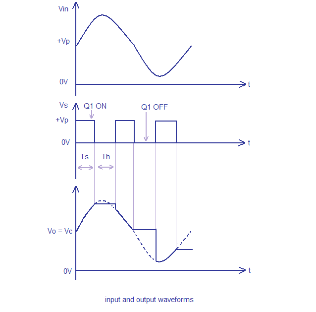
The time periods of the Vs during which the voltage across the capacitor (Vc) is equal to Vin are called sample periods (Ts) and the time periods of Vs during which the voltage across the capacitor C1 (Vc) is held constant are called hold periods (Th). Taking a close look at the input and output wave forms of the circuit will make it easier to understand the working of the circuit.

Circuit diagram

 Sample and Hold circuit using uA741 opamp

Input and output waveforms.

sample and hold waveforms
Input and output waveforms - Sample and hold circuit

Notes

  • The circuit can be assembled on a vero board.
  • Use +15V/-15V DC dual supply for powering the opamp.
  • Capacitor C1 must have minimum leakage current possible and thats why a polyester capacitor is used here.
  • Mount the IC uA741 on a holder.
  • The type number of the MOSFET Q1 is not very significant here and so substitution is possible if BS170 is not available.
  • BS170 is a 60V, 500mA n-channel enhancement mode MOSFET available in TO-92 package.
  • Preset resistor R1 can be used for offset adjustments.
Read More..

Simple Regenerative Receiver Circuit Diagram 80m or 40m

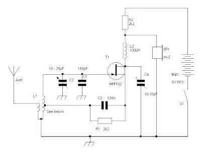
This is a simple design, can have excellent results, he is a recipient of regeneration, if you have never built any receiver, this is one you will build Easy. The circuit described is simple and has many limitations in sensitivity and selectivity, but is able to receive signals from radio amateurs (40m or 80m) in SSB and CW, and as output using a small headset crystal. 

He will have a saturation if there are strong stations available on AM broadcast band of 41m at night.L1 is a small toroid T50-2 (red) with about 18 to 20 times (40m) or 35 to 40 times (80m) in the main winding connected to the FET with a single coupling circuit facing the antenna connection. 

The center tap is about 20% of the primary winding. C1 is adjusted to set the radio band to the 40m and C2 then acts as a fine tuning within the band.The supply of 12 to 14V, R2 should be increased 5K6 or 6K8 output will be higher and similar sensitivity to-100dBm (about 2uV).

Regenerative Receiver Circuit Diagram

Regenerative Receiver Circuit Diagram

Read More..

Monday, October 20, 2014

Simple 8 Watt Audio Power Amplifier Schematic

Here is the schematic for an 8 watt audio power amplifier. This amp can be used as a simple booster, the heart of a more complicated amplifier or used as a guitar amp. It is very small and portable unit and can be powered through 12V battery. I built the circuit on a Vero Board and had to add extra inductors, capacitors and resistors to prevent oscillation.

Circuit diagram:
 8 Watt Audio Power Amplifier Schematic Circuit Diagram
8 Watt Audio Power Amplifier Circuit Diagram

Parts:

R1 = 47K
R2 = 2.2R/1W
R3 = 220R/1W
R4 = 2.2R/1W
C1 = 100nF-63V
C2 = 10uF-25V
C3 = 470uF-25V
C4 = 2000uF-25V
C5 = 100nF-63V
IC1 = LM383
SPKR = 4ohm/8W

Notes:
  • IC1 must be installed on a heat sink.
  • C1 is for filtering and to prevent oscillation and should not be omitted.
  • The circuit can be built on a Vero Board, universal solder board or PC board, the PC board is preferred.
  • The circuit draws about 880Ma at 12 V.
  • By swapping the values of R2 and R3; you can turn this amplifier into a guitar amp with no preamp required.
  • If you cant find 2000uF, then replace C4 with a 2200uF unit.
  • If you add a 0.2uF capacitor in series with a 1 ohm resistor to the output you can prevent oscillation of the circuit under certain conditions.
Read More..

Simple Novel Buzzer Circuit Diagram

This Simple Novel Buzzer Circuit Diagram uses a relay in series with a small audio transformer and speaker. When the switch is pressed, the relay will operate via the transformer primary and closed relay contact. As soon as the relay operates the normally closed contact will open, removing power from the relay, the contacts close and the sequence repeats, all very quickly. So fast that the pulse of current causes fluctuations in the transformer primary, and hence secondary. The speakers tone is thus proportional to relay operating frequency. The capacitor C can be used to "tune" the note. The nominal value is 0.001uF, increasing capacitance lowers the buzzers tone.

Simple Novel Buzzer Circuit Diagram

Read More..

Friday, October 17, 2014

Simple Sound Activated Switch

Control by sound may be very useful,  not just on a robot but also for a bit  of home automation, for example a  sound activated light responding to a  knock on the door or a hand clap. The  light will be automatically switched  off after a few seconds. An alternative  use is burglar protection — if someone  wants to open the door or break some-thing the light will come on, suggesting  that someone’s at home. The circuit can work from any 5– 12 VDC regulated power supply pro-vided a relay with the suitable coil voltage is used.
 
Simple Sound Activated Switch Circuit diagram :


Sound Activated Switch Circuit Diagram

When you first connect the supply  voltage to the circuit, the relay will  be energised because of the effect of capacitor C2. Allow a few seconds for  the relay to be switched off. You can  increase or decrease the ‘on’ period  by changing the value of C2. A higher  value results in a longer ‘on’ period,  and vice versa. Do not use a value  greater than 47 µF. Biasing resistor R1 determines to a  large extent the microphone sensitivity. An electret microphone usually has  one internal FET inside which requires  a bias voltage to operate. The optimum  bias level for response to sound has to  be found by trial and error.
Read More..

Thursday, October 16, 2014

Simple 500W Inverter 12 Volt to 220 Volt Circuit Diagram

This is the Simple 500W Inverter 12 Volt to 220 Volt Circuit Diagram about the the inverter, because like working outdoors, or to backup storage to use when necessary. Most of this is circuit low power, which is not suitable for practical applications. My friends said that he would be about 500 Watt. It is a good size. Use with television receivers and light bulbs as well. When looking for circuit. I get headaches. 

500W Inverter 12 Volt to 220 Volt Circuit Diagram
 
500W

If you are a beginner or I can not buy expensive good quality circuits. Requires only one transistor. Or if you have free time. I want to build old circuit is alive again. This circuit will accommodate all your needs. It is a simple circuit. The same principle, I take battery voltage 12V to produce a oscillator about 100 Hz and pass to a two frequency divider circuit is only 50HZ. and drive a 10 ampere transformer with 10 x 2N3055 transistor in parallel. 

By a single transistor has 2A, when I use 10 transistors or 5 pairs of drive high current output. The complexity of circuit, but the principle is not it, and it is the number of transistors on a basic, easy to buy. You may be modified 100 watt power inverter To the size of transistors and transformers as well. 

Note:
If you think that This circuit is not good enough. For your work. It is hard to find equipment. You do not have it now. These circuits may be viewed below. It may be appropriate for you.


Source: leksound project

Read More..

Simple Complementary Push Pull Power Amplifier Circuit

This amplifier circuit is very popular audio power amplifier circuit type. We call it a complementary since the final transistors is an NPN-PNP pair, each with the same characteristics. This circuit produce an AB class amplifier, since each transistor works in slightly more than half cycle of the signal. There is overlap area when both transistor conduct a current, and this area will be around its stationary current (when the input signal is zero). This circuit is also known as push-pull amplifier circuit since each transistor in the pair is working alternatively. Here is the schematic diagram of the circuit:

 Complementary (Push-Pull) Power Amplifier Circuit Diagram

Read More..

Simple Data accretion System Circuit Diagram

In this circuit, an HA-4900 series comparator is used in conjunction with a D/A converter to form a simple,


Simple

versatile, multichannel analog input for a data acquisition system. The processor first sends an address to the D/A, then the processor reads the digital word generated by the comparator outputs, lb perform a simple comparison, the processor sets the D/A to a given reference level, then examines one or more comparator outputs to determine if the inputs are above or below the reference. A window comparison consists of two such cycles with two reference levels set by the D/A. One way to digitize the inputs would be for the processor to increment the D/A in steps. The D/A address, as each comparator switches, is the digitized level of the input. While stairstepping, the D/A is slower than successive approximation; all channels are digitized during one staircase ramp.
Read More..

Simple Knight Rider lights Circuit for model cars

This simple circuit drives 6 LEDs in Knight Rider scanner mode. Power consumption depends mainly on the type of LEDs used if you use a 7555 (555 CMOS version).


Simple Knight Rider lights Circuit

Simple


Note
That VDD and GND for the ICs are not shown in the circuit drawing.

Pin-outs:
(7)555 4017
1 GND 1 Q5 9 Q8
2 TRIGGER 2 Q1 10 Q4
3 OUTPUT 3 Q0 11 Q9
4 RESET 4 Q2 12 CO
5 CONTROL VOLTAGE 5 Q6 13 NOT ENABLE
6 THRESHOLD 6 Q7 14 CLK
7 DISCHARGE 7 Q3 15 RESET
8 VDD 8 GND 16 VDD
Read More..

Wednesday, October 15, 2014

Simple Stereo Indicator Detects L R Signal Difference

This true stereo indicator is different from what we usually find on FM radio receiver, which is usually a pilot tone detector. A stereo broadcast from FM radio station contain pilot tone, but a presence of pilot tone doesn’t necessarily a stereo broadcast signal since a mono FM transmitter ca broadcast pilot tone as well.  Since this circuit detect the difference between left and right channel, this circuit can detect a real stereophonic programs. 

When there is no difference between R and L input signals, the output A1 and output A2 is at the same potential. That will make a a virtual ground rail at half the supply voltage. Here is the schematic diagram of the circuit. The A1 will supply a negative or positive voltage when A1 detects a difference between R and L input signals with respect to the virtual ground rail. 

The C4 will be charged via D2 an C3 via D1. The LED is turned on by the comparator A3/A4 via OR circuit D3/D4. The input signal level should be greater than 100mV to compensate for the drop across D2 or D1. P1 is used to adjust the sensitivity of stereo indicator.

 Stereo Indicator Detects L-R Signal Difference Circuit Diagram


Read More..

Sunday, October 5, 2014

A Simple Crossover Circuit for Tweeter

A single coil speaker is not good in handling high and low frequency at the same time. If we could filter out the low frequency and play it through a tweeter, it will produce more sound quality than using a single speaker. In this figure shows the answer for the problem in above. This is a simple design circuit for protected thee voltage and current in tweeter speaker.


The concept of operation this circuit is the speaker that can protected is tweeter with 4 or 8 ohm impedance. R1 is a potentiometer resistor that used to adjust matching the tweeter speaker output level to that of woofer. R1 should be rated more than 2 Watts.
Read More..

Friday, October 3, 2014

Simple Electrification Circuit Unit

Here’s a design circuit that is intended for carrying out harmless experiments with high-voltage pulses and functions in a similar way as an electrified fence generator. The p.r.f. (pulse repetition frequency) is determined by the time constant of network R1-C3 in the feedback loop of op amp IC1a: with values as specified, it is about 0.5 Hz. The stage following the op amp, IC1b, converts the rectangular signal into narrow pulses. Differentiating network R2-C4, in conjunction with the switching threshold of the Schmitt trigger inputs of IC1b, determines the pulse period, which here is about 1.5 ms. The output of IC1b is linked directly to the gate of thyristor THR1, so that this device is triggered by the pulses. Here’s the figure of the schematic diagram;


The requisite high voltage is generated with the aid of a small mains transformer, whose secondary winding is here used as the primary. This winding, in conjunction with C2, forms a resonant circuit. Capacitor C3 is charged to the supply voltage (12 V) via R3.When a pulse output by IC1b triggers the thyristor, the capacitor is discharged via the secondary winding. The energy stored in the capacitor is, however, not lost, but is stored in the magnetic field produced by the transformer when current flows through it. When the capacitor is discharged, the current ceases, whereupon the magnetic field collapses. This induces a counter e.m.f. in the transformer winding which opposes the voltage earlier applied to the transformer. This means that the direction of the current remains the same. However, capacitor C2 is now charged in the opposite sense, so that the potential across it is negative. When the magnetic field of the transformer has returned the stored energy to the capacitor, the direction of the current reverses, and the negatively charged capacitor is discharged via D1 and the secondary winding of the transformer. As soon as the capacitor begins to be discharged, there is no current through the thyristor, which therefore switches off. When C2 is discharged further, diode D1 is reverse-biased, so that the current loop to the transformer is broken, whereupon the capacitor is charged to 12 V again via R3. At the next pulse from IC1b, this process repeats itself.
Read More..

Thursday, October 2, 2014

Simple Dual Symmetrical Power Supply Circuit

This circuit is of interest not merely because it uses a bell transformer with a single secondary winding to provide symmetrical voltages for low current applications but also because the final output voltages are greater than the normal bell transformer (220 V/8 V) output. In fact the final output can be as much as twice this value.
This multiplication is achieved using two voltage doublers each consisting of two diodes and two capacitors, connected head to tail. Each diode/capacitor couple takes every alternate half cycle of the sinusoidal voltage such that the output voltage U is (theoretically) equal to 2/2 U8ff_, where Uefg is the effective output voltage of the transformer. A current of 150 . . .200 mA and 1 V of ripple can be expected using the capacitor values shown here. In order to increase this current without a similar increase in ripple the values of the capacitors may be made greater but C1 must be approximately the same as C2, and C3 about the same as C4. To get a stable symmetrical output of i 15 V two voltage regulators, a 7815 and a 7915, should be used. This will then allow a bell transformer to be used for any small circuits with operational amplifiers requiring a symmetrical supply of 14 or 15 V and a current of 0.1 .. .0.2 A.


Read More..

Simple Mains Undervoltage Overvoltage Circuit Diagram


For making adjustments, first remove C2 from the circuit to avoid delay which will confuse the matter unnecessarily. Set potentiometer VRI to get monitor voltage VM of 7V with nominal 220V supply. VR2 controls the lower limit and VR3 controls the higher limit. Initially keep VR2 in the lowermost position so that voltage at pin number 3 is minimum, and keep VR3 in the uppermost position so that voltage at pin number 6 is maximum. In this condition the window limits are wide open and the relay should operate. Nominal operating limits are between I80V and 250V. s lf the monitoring voltage is 7V with nominal 220V AC supply, then set VR2 to give 5V at pin number 3 and VR3 to give 8 V at pin number 6. Make a simple check before use. Adjust VRI to reduce the voltage VM below 5V or to increase . the voltage VM above 8V. In both cases, the relay should de- energize. If it does, bring back VM to 7V again and leave it there. Now the cutout is ready for use. Precise voltage settings can be made by varying the input supply using a variac. With a 220V supply, set VRI to give a monitor voltage of 7V; with l80V input, set VR2 to just de-energise the relay; and then with 250V input, set VR3 to just de-energise the relay. Now connect C2, as shown in Fig. 2, to get back the delay feature.

This device ensures safety and protection to your gadgets, but will not regulate the power supply. If the voltage excursions are too much and too often, or if uninterrupted operation is required along with safety, use this cutout in addition to a voltage regulator. V The load current is limited by the relay contact ratings. Therefore care should be taken to avoid using it with high current load. Otherwise, suitably modify the relay for higher currents. The stability of voltage limits depends mainly on the . potentiometers. Use good-quality potentiometers, either cermet or wirewound types. Do not try to use the usual trimpots instead. 

PARTS LIST

IC1 —747C integrated circuit, I0-pin metal case ·
T1  —SL I00 (SEM) transistor
T2 —BC 108c (BEL) transistor
T3 -—BC177 (BEL) transistor
D1-D4 —Selenium rectifier bridge or BY 126 (4 Nos.)
D5 ——Zener diode, BZX6l—Cl2 (BEL)IW
D6-DI0 —BYl26 diodes
R1 —-500-0hm, I/2 W resistor
R2 -5.1kilohm, % W resistor
R3, R7 —10-kilohm, IA W resistor
R4 -500kilohm trimpot (variable resistor)
R5, R6 —1kilohm, I4 W resistor
R8 —1megohm, % W resistor -
VRI-VR3 -5-kilohm wirewound potentiometers (see text)
C1-500 uF/25V electrolytic
C2 — 500 pF/l2V electrolytic
C3 —— 0.68uF400Vbipolar or electrolytic .
C4 — 2000uF,I2V electrolytic
NI — Neon bulb
R -9V, 20mA relay (see text)
Xl -220V to I5V step-down transformer 
Read More..

Simple Transistor Hfe Tester Circuit Diagram Using IC 741

  1. P1 is used to set a reference voltage derived from voltage UXY UD1 (or D2 for a PNP transistor). This means that l the setting of the potentiometer is directly proportional to the hpp; of the transistor under test and is independent of supply voltage.
  2. The voltage across R2 and the voltage set with P1 are compared by lC1 which is connected as a comparator. Potentiometer P1 is now set so that the LED at the output of the op-amp just lights or is just dimmed.
  3. This hfe tester is interesting because of its simplicity and because it enables the B of both PNP and NPN transistors to be measured.
  4. At this setting the voltage across the potentiometer is equal to the voltage across R2. Switch S1 is used to switch from NPN to PNP (or vice versa) by reversing the polarity of voltage UXY.
  5. LEDs D3 and D4 in the supply lines ensure that the input voltages to be measured are within the common mode range of the opamp used.
  6. Furthermore the measurement is independent of the supply voltage of the tester. As the diagram shows, the base current of the transistor under test travels via R1. Its base current IB is thus equal to The voltage drop across the collector resistor is hfe x IB x R2.
Read More..

Wednesday, October 1, 2014

Simple Function Generator Circuit Triangle and Square Wave Generator Circuit

The post explains how to make a function generator circuit for generating triangle waves and square waves with variable parameters and by using a single chip.
This is a downright simple design for an AF function generator that supplies a rectangular and triangular signal, and can be fed from a single 9 V supply. The signal generator proper is a Type TLC272 dual CMOS opamp from Texas Instruments. This chip is remarkable for its low current consumption and wide operating range. The circuit is essentially com- posed of two functional parts. Opamp A1 is connected to function as a Schmitt-trigger whose toggle point is set to 4.5 V, while Az is an integrator that converts the rectangular signal from A1 into a triangular waveform. The oscillation frequency of the circuit is fixed solely by the ratio R/C and can be calculated from f = Rz/4RRC. Resistor R may be replaced by the combination of the l0K resistor and l0OK potentiometer as shown to effect continuous adjustment of the output frequency within the AF signal band. The generator should not be terminated in less than 10K.


Circuit diagram for the simple function generator circuit. Triangle wave and square wave generator circuit.


Read More..

Tuesday, September 23, 2014

Simple Class A Power Amplifier by IRF530

Simple

I was in need of high quality headphones amplifier because of many reasons and decided to build SDS Labs phone amp. This is extremely rewarding project in a sense that it is fully documented, includes PCB, parts list and building notes – so it’s easy to build and then it sounds great.

I have used IRF530 and IRF9530 pairs and they work just fine given the fact that you add 100-300 Ohm gate resistors to prevent high frequency oscillations. This is a common problem for MOSFET designs and if you don’t have a good oscilloscope or want to be on the safe side just use gate resistors on any MOSFET design. Ferrite beads put over gate pin could also be used instead but I somehow prefer resistors.

Read More..

Thursday, September 18, 2014

Simple UPS Power Supply Circuit Diagram

This is a Simple UPS Power Supply Circuit Diagram. This circuit is a simple form of the commercial UPS, the circuit provides a constant regulated 5 Volt output and an unregulated 12 Volt supply. In the event of electrical supply line failure the battery takes over, with no spikes on the regulated supply.

Simple UPS Power Supply Circuit Diagram


http://saaqibs.blogspot.com/2014/06/simple-ups-power-supply-circuit-diagram.html


Notes:
This circuit can be adapted for other regulated and unregulated voltages by using different regulators and batteries. For a 15 Volt regulated supply use two 12 Volt batteries in series and a 7815 regulator. There is a lot of flexibility in this circuit.

TR1 has a primary matched to the local electrical supply which is 240 Volts in the UK. The secondary winding should be rated at least 12 Volts at 2 amp, but can be higher, for example 15 Volts. FS1 is a slow blow type and protects against short circuits on the output, or indeed a faulty cell in a rechargeable battery. LED 1 will light ONLY when the electricity supply is present, with a power failure the LED will go out and output voltage is maintained by the battery. The circuit below simulates a working circuit with mains power applied:

Between terminals VP1 and VP3 the nominal unregulated supply is available and a 5 Volt regulated supply between VP1 and VP2. Resistor R1 and D1 are the charging path for battery B1. D1 and D3 prevent LED1 being illuminated under power fail conditions. The battery is designed to be trickle charged, charging current defined as :-
(VP5 - 0.6 ) / R1
where VP5 is the unregulated DC power supply voltage.
D2 must be included in the circuit, without D2 the battery would charge from the full supply voltage without current limit, which would cause damage and overheating of some rechargeable batteries. An electrical power outage is simulated below:

Note that in all cases the 5 Volt regulated supply is maintained constantly, whilst the unregulated supply will vary a few volts.

Standby Capacity
The ability to maintain the regulated supply with no electrical supply depends on the load taken from the UPS and also the Ampere hour capacity of the battery. If you were using a 7A/h 12 Volt battery and load from the 5 Volt regulator was 0.5 Amp (and no load from the unregulated supply) then the regulated supply would be maintained for around 14 hours. Greater A/h capacity batteries would provide a longer standby time, and vice versa.


Author:Andy Collinson, anc@mitedu.freeserve.co.uk
Read More..