Showing posts with label amplifier. Show all posts

Wednesday, November 5, 2014

4 X 15 Watt Mini Power Amplifier

A lot of electronic circuits in the domain of audio amplifiers are already been published here. This circuit is a little different because it is a four channel amplifier. Each channel of this amplifier can deliver an output of 15Watts into a 4 ohm speaker. The amplifier can be operated from a single 12V DC supply and this makes it possible to use this amplifier in car audio applications too.

4 X 15 Watt Mini Power Amplifier Circuit Diagram :

4X15W-amplifier-circuit

The circuit is based on the 15W BTL X 2 channel audio power amplifier IC TA8215 from Toshiba. Even though chip is specifically designed for car audio applications it can be also used for home audio applications. Two TA8215 ICs are used here in order to obtain a 4 channel amplifier system. The circuit is designed almost exactly as per the application diagram in the ICs datasheet. Pins 7 and 19 are the Vcc pins of the ICs internal integrated power amplifier stages and these pins are connected to the positive supply. Pin 9 is the Vcc pin for ICs internal preamplifier and it is also connected to the positive supply. Pins 13 and 14 are the internal power amplifiers ground pins and they are tied together and connected to the ground.

The internal preamplifier’s ground pin (pin5) is connected to the common ground through a 10 Ohm resistor which makes the input ground separated from the common ground by a resistance of 10 ohms and this improves the noise rejection. The 100uF capacitor works as a power supply de-coupler. The resistor networks connected to the output lines of each amplifier improves the high frequency stability. The variable resistors (R3, R4, R12 and R13) works as the volume controller for the corresponding channels.

Notes :
  • Assembling the circuit on a good quality PCB is a must for obtaining optimum sound quality.
  • Use 12V DC for powering the circuit.
  • The ICs must be fitted with adequately sized heat sinks.
  • R3, R4, R12 and R13 serves as volume controllers.
  • K1 to K4 can be 4 Ohm, 20W speakers.
  • This amplifier circuit can be used in a variety of applications such as car audio systems, home theater systems, personal audio systems, public address systems etc.


Read More..

Tuesday, November 4, 2014

Stereo Power Amplifier Circuit based on BA5417

BA5417 is a stereo amplifier IC with a lot of good features like thermal shut down, standby function, soft clipping, wide operating voltage range etc. The IC can deliver 5W per channel into 4 ohm loud speakers at 12V DC supply voltage. The BA5417 has excellent sound quality and low THD (total harmonic distortion) around 0.1% at F=1kHz; Pout=0.5W.

Stereo Power Amplifier  Circuit diagram :

stereo-amplifier-circuit

Setup and working of this stereo power amplifier circuit is somewhat similar to the BA5406 based stereo amplifier circuit published previously. C10 and C11 are DC decoupling capacitors which block any DC level present in the input signals. C2 and C6 couples the amplifiers left and right power outputs to the corresponding loud speakers. C1 and C5 are bootstrap capacitors.

Bootstrapping is a method in which a portion of the amplifiers is taken and applied to the input. The prime objective of bootstrapping is to improve the input impedance. Networks R1,C3 and R2,C7 are meant for improving the high frequency stability of the circuit. C4 is the power supply filter capacitor. S1 is the standby switch. C8 is a filter capacitor. R3 and R4 sets the gain of the left and right channels of the amplifier in conjunction with the 39K internal feedback resistors.
Note :
  • Supply voltage range of BA5417 is from 6 to 15V DC.
  • The recommended supply voltage for this circuit is 12V DC.
  • The power supply must be well regulated and filtered.
  • BA5417 requires a heatsink.
  • The circuit can be assembled on a perf board without much degradation in performance.


Read More..

Monday, October 27, 2014

Most Power Supply for Amplifier

As with most power amplifiers, the ±60 V power supply need not be regulated. Owing to the relatively high power output, the supply needs a fairly large mains transformer and corresponding smoothing capacitors—see circuit diagram below.

Note that the supply shown is for a mono amplifier; a stereo outfit needs two supplies. 

The power supply is straightforward, but can handle a large current. Voltage acserves as drive for the power-on delay circuit. The transformer is a 625 VA type, and the smoothing capacitors are 10 000 µF, 100 V electrolytic types. The bridge rectifier needs to be mounted on a suitable heat sink or be mounted directly on the bottom cover of the metal enclosure.. The transformer needs two secondary windings, providing 42.5 V each. The prototype used a toroidal transformer with 2x40 V secondaries. The secondary winding of this type of transformer is easily extended: in the prototype 4 turns were added and this gave secondaries of 2x42.5 V.
Read More..

60W Dual Stereo Power Amplifier

A portion of electronic circuits into the domain of audio amplifiers are already been available at this juncture. This circuit is a hardly singular for the reason that it is a four channel amplifier. each one channel of this amplifier can furnish with an output of 15Watts into a 4 ohm amplifier. The amplifier can subsist operated from a single 12V DC supply and this makes it likely to spend this amplifier happening car audio applications too.

The circuit is based on the 15W BTL X 2 channel audio power amplifier IC TA8215 from Toshiba. Even though whittle is specifically designed designed for car audio applications it can stay and used for to your place audio applications. Two TA8215 ICs are used now in order to gain a 4 channel amplifier practice. The circuit is designed almost exactly in the role of for each the use diagram within the ICs datasheet. Pins 7 and 19 are the Vcc pins of the ICs inner integrated power amplifier stages and these pins are connected to the optimistic supply. Pin 9 is the Vcc pin in lieu of ICs interior preamplifier and it is additionally connected to the positive supply. 

60W Dual Stereo Power Amplifier
Pins 13 and 14 are the domestic power amplifiers ground pins and they are fixed cool and connected to the ground. The in-house preamplifier’s ground pin (pin5) is connected to the regular ground through a 10 Ohm resistor which makes the input ground separated from the common ground by a resistance of 10 ohms and this improves the sound rejection. The 100uF capacitor workings in the function of a power supply de-coupler. The resistor networks connected to the output defenses of both amplifier improves the far above the ground frequency stability. The movable resistors (R3, R4, R12 and R13) facility as the volume controller intended for the corresponding channels.
Read More..

Sunday, October 26, 2014

25W Hi Fi Audio Amplifier LM1875

This circuit is the audio amplifier circuit has a very all the rage single.This is a down-to-earth circuit. miniature pieces of equipment. And Watt are climax.The circuit uses IC figure LM1875, which is under the protection circuit IC output before Too tiny circuit. And a important distortion because low as 0.015% on a frequency of 1kHz.

25W Hi-Fi Audio Amplifier Circuit Diagram
This circuit uses helpful, unconstructive ground power supply to move the audio show with both halves of the signal swing, positive and negative halves,The sound so as to came not permitted rock apparent.production is. as soon as paying into the audio input. Audio is through R1, R2, C1 and R3 to limit the audio sign appropriately.And limit the racket to the input signal assorted down to the ground.next sends a signal to racket to the input pin of IC 1.A noninterting pin, amplifier non-return time.Out of the 4 output pins to access the speakers.The R6 and C4 eliminate racket miscellaneous with the output down to the ground.And a new part of the audio output pin 4 of integrated circuit bidding befall fed back into place through R5 to pin 2, which R4 and R5 determines the rate of boost up, can be calculated from R5/R4,will expansion equal to 15 era, With a C2 to experience high-pitched frequencies better.
Read More..

Saturday, October 25, 2014

25 Watt Audio Amplifier Circuits Diagram

25 Watt Audio Amplifier Circuits Diagram

25 Watt Audio Amplifier Circuits Diagram

Parts:

R1,R4_________47K  1/4W Resistors
R2____________4K7  1/4W Resistor
R3____________1K5  1/4W Resistor
R5__________390R   1/4W Resistor
R6__________470R   1/4W Resistor
R7___________33K   1/4W Resistor
R8__________150K   1/4W Resistor
R9___________15K   1/4W Resistor
R10__________27R   1/4W Resistor
R11_________500R   1/2W Trimmer Cermet
R12,R13,R16__10R   1/4W Resistors
R14,R15_____220R   1/4W Resistors
R17___________8R2    2W Resistor
R18____________R22   4W Resistor (wirewound)
 
C1___________470nF  63V Polyester Capacitor
C2___________330pF  63V Polystyrene Capacitor
C3,C5________470µF  63V Electrolytic Capacitors
C4,C6,C8,C11_100nF  63V Polyester Capacitors
C7___________100µF  25V Electrolytic Capacitor
C9____________10pF  63V Polystyrene Capacitor
C10____________1µF  63V Polyester Capacitor
 
Q1-Q5______BC560C   45V 100mA Low noise High gain PNP Transistors
Q6_________BD140    80V 1.5A PNP Transistor
Q7_________BD139    80V 1.5A NPN Transistor
Q8_________IRF530  100V 14A N-Channel Hexfet Transistor
Q9_________IRF9530 100V 12A P-Channel Hexfet Transistor
 

Power supply circuit diagram


Power supply circuit diagram


Parts:

R1____________3K3  1/2W Resistor C1___________10nF 1000V Polyester CapacitorC2,C3______4700µF   50V Electrolytic CapacitorsC4,C5_______100nF   63V Polyester Capacitors D1__________200V 8A Diode bridgeD2__________5mm. Red LED F1,F2_______3.15A Fuses with sockets T1__________220V Primary, 25 + 25V Secondary 120VA Mains transformer PL1_________Male Mains plug SW1_________SPST Mains switch
 

Notes:

  • Can be directly connected to CD players, tuners and tape recorders. Simply add a 10K Log potentiometer (dual gang for stereo) and a switch to cope with the various sources you need.
  • Q6 & Q7 must have a small U-shaped heatsink.
  • Q8 & Q9 must be mounted on heatsink.
  • Adjust R11 to set quiescent current at 100mA (best measured with an Avo-meter connected in series to Q8 Drain) with no input signal.
  • A correct grounding is very important to eliminate hum and ground loops. Connect to the same point the ground sides of R1, R4, R9, C3 to C8. Connect C11 to output ground. Then connect separately the input and output grounds to power supply ground.
  • An earlier prototype of this amplifier was recently inspected and tested again after 15 years of use.

Technical data:

Output power:
well in excess of 25 Watt RMS @ 8 Ohm (1KHz sine wave)
Sensitivity:
200mV input for 25W output
Frequency response:
30Hz to 20KHz-1dB
Total harmonic distortion @ 1KHz:
0.1W 0.014% 1W 0.006% 10W 0.006% 20W0.007% 25W 0.01%
Total harmonic distortion @10KHz:
0.1W 0.024% 1W 0.016% 10W 0.02% 20W0.045% 25W 0.07%
Unconditionally stable on capacitive loads
Read More..

Friday, October 24, 2014

25 Watt Audio Amplifier Circuits Diagram

25 Watt Audio Amplifier Circuits Diagram

25 Watt Audio Amplifier Circuits Diagram

Parts:

R1,R4_________47K  1/4W Resistors
R2____________4K7  1/4W Resistor
R3____________1K5  1/4W Resistor
R5__________390R   1/4W Resistor
R6__________470R   1/4W Resistor
R7___________33K   1/4W Resistor
R8__________150K   1/4W Resistor
R9___________15K   1/4W Resistor
R10__________27R   1/4W Resistor
R11_________500R   1/2W Trimmer Cermet
R12,R13,R16__10R   1/4W Resistors
R14,R15_____220R   1/4W Resistors
R17___________8R2    2W Resistor
R18____________R22   4W Resistor (wirewound)
 
C1___________470nF  63V Polyester Capacitor
C2___________330pF  63V Polystyrene Capacitor
C3,C5________470µF  63V Electrolytic Capacitors
C4,C6,C8,C11_100nF  63V Polyester Capacitors
C7___________100µF  25V Electrolytic Capacitor
C9____________10pF  63V Polystyrene Capacitor
C10____________1µF  63V Polyester Capacitor
 
Q1-Q5______BC560C   45V 100mA Low noise High gain PNP Transistors
Q6_________BD140    80V 1.5A PNP Transistor
Q7_________BD139    80V 1.5A NPN Transistor
Q8_________IRF530  100V 14A N-Channel Hexfet Transistor
Q9_________IRF9530 100V 12A P-Channel Hexfet Transistor
 

Power supply circuit diagram


Power supply circuit diagram


Parts:

R1____________3K3  1/2W Resistor C1___________10nF 1000V Polyester CapacitorC2,C3______4700µF   50V Electrolytic CapacitorsC4,C5_______100nF   63V Polyester Capacitors D1__________200V 8A Diode bridgeD2__________5mm. Red LED F1,F2_______3.15A Fuses with sockets T1__________220V Primary, 25 + 25V Secondary 120VA Mains transformer PL1_________Male Mains plug SW1_________SPST Mains switch
 

Notes:

  • Can be directly connected to CD players, tuners and tape recorders. Simply add a 10K Log potentiometer (dual gang for stereo) and a switch to cope with the various sources you need.
  • Q6 & Q7 must have a small U-shaped heatsink.
  • Q8 & Q9 must be mounted on heatsink.
  • Adjust R11 to set quiescent current at 100mA (best measured with an Avo-meter connected in series to Q8 Drain) with no input signal.
  • A correct grounding is very important to eliminate hum and ground loops. Connect to the same point the ground sides of R1, R4, R9, C3 to C8. Connect C11 to output ground. Then connect separately the input and output grounds to power supply ground.
  • An earlier prototype of this amplifier was recently inspected and tested again after 15 years of use.

Technical data:

Output power:
well in excess of 25 Watt RMS @ 8 Ohm (1KHz sine wave)
Sensitivity:
200mV input for 25W output
Frequency response:
30Hz to 20KHz-1dB
Total harmonic distortion @ 1KHz:
0.1W 0.014% 1W 0.006% 10W 0.006% 20W0.007% 25W 0.01%
Total harmonic distortion @10KHz:
0.1W 0.024% 1W 0.016% 10W 0.02% 20W0.045% 25W 0.07%
Unconditionally stable on capacitive loads
Read More..

Low distortion audio amplifier

This is an unusual circuit for an ultra-low distortion power amp. According to my original notes the circuit is dated January 1977 so the circuit is not exactly modern but it is still sufficiently different to be interesting. The circuit was designed and sold as a card by a purveyor of surplus components but, even using mostly manufacturers rejected transistors, we managed to get about 0.02% total harmonic distortion at 30 watts with a ±25v power supply into 8 ohms.: no bad figure even in these days of MOSFET and ICs. In 1977 anything below 0.1% was considered excellent. And this figure was pretty repeatable without doing much selection.
The problem of course is that since I havent touched this amplifier for many a year I have absolutely no idea what modern transistor types one should use for it but they are not critical: output transistors and drivers need to be the correct type but the other transistors can be small signal types - as long as they can handle the full voltage between + and - supplies.
Circuit: pwramp.gif

Tr1 and Tr2 are a long-tailed pair (LTP to save typing). It is quite common to have a LTP in an audio amp but this is different: this is a complimentary LTP. As far as I am aware no one else had used a complimentary LTP at the time, though I have since seen it used in one other circuit. So I guess the circuit is unique to the author. One of the things that limits the performance of a conventional LTP is that the tail source loads the common emitters. In a complementary LTP this cant happen as there is no tail current source so that all the current of one transistor has to flow through the other. 

Tr2s collector current flows into D1 and D2 which develop a voltage: this is used to bias Tr8 as a constant current source for Tr4s collector. The fact that Tr4 is working at a constant current defines its base-emitter voltage which must be developed across R4. This defines a current in R4 and this is the current that the LTP must operate at - so the ring of four transistors (Tr1, 2, 3, & 4) is self biasing and all transistors work at their best with minimum unwanted loads and biasing detracting from the performance. Tr4 is actually one of the most critical transistors: in the original circuit it was selected for Vce greater than 75v. Most Texas BC212s passed easily. Lower voltage transistors caused an increase in distortion level. 

There is always a down side to any circuit: in the conventional LTP the base-emitter voltages tend to cancel each other out. In the complimentary LTP they add so there is a drop of about 1.2v between the two bases: this must be cancelled in the biasing chain and, since this circuit was designed for operation over a wide range of supply voltage, I had to be a little clever. Because of the constant current operation of the LTP and the constant voltage drop across D1 & D2, there is also a constant voltage across R14. This drop is used to lift up the bottom of the biasing chain (R1 and R11) so that the output sits at around half supply voltage, over a wider supply range. 

D3 and D4 develop a bias voltage so that the output transistors are at the correct point, slightly conducting, to minimise crossover distortion. 

The output transistors are complimentary (the original design used MJE2011 and MJE2021) and are driven by complimentary drivers: PNP driving NPN and vice versa. This arrangement is not only pleasingly symmetrical but gives better performance that the more common Darlington arrangement - the full gain of all the transistors is used and there is more internal feedback and less voltage drop. 

The output current is monitored in the two resistors R7 and R22 (180 milliohms). The current limiting is unusual in that it works inside the input ring at an earlier stage than normal. This has an advantage that the current limiting transistors do not load the drive circuitry - which will introduce distortion. The slight down side is that there may be a slight tendency to oscillation when in current limit. R3 and R14 are necessary to restrict the current availability when the current limit engages. R5 and R19 are present to make the current limit vary with the voltage across the power transistors to avoid the second breakdown region of power transistors. 

The points shown connecting terminals 1-2 and 6-7 are scratch-through tracks. 1 and 2 are the power and signal earths: to keep distortion in a stereo system to a minimum the currents in these must never share the same path so in a stereo system four earth wires are run to the systems common earth point - a spider common earth - and this means breaking the link. The link between 6 & 7 is in the feedback path and there are times when this can usefully be broken - one cheapskate was to fit a tone control circuit here (see below). It works fine but is a bit of an insult to such a low-distortion design!. A third break point is in the collector of Tr2. Breaking this shuts down the amplifier completely and safely. Is a thermal switch is to be fitted, this is the place. 

Overall negative feedback is in two parts: D.c. is fed back via R13: there is 100% d.c. feedback. A.c. feedback is via R12 and R17. Note the output capacitor is inside this feedback loop (speaker connects between terminal 5 and negative) which extends the low frequency response. 

Another feature is the accessibility of both ends of the output coupling capacitor: being designed for a junk shop, they didnt want to use expensive capacitors! So for extra bass performance an additional capacitor can easily be connected. 

The circuit can also be driven as a low input impedance: break 6-7, short pin 8 to C4s positive and apply input to pin 6. In this mode the input distortion is actually better: my original notes show as low as 0.01%!
When building a low-distortion amplifier, layout is vital. In fact to get distortion around 0.02% requires a lot of skill and experience. The problem is that the current in the output stage alternates between the two power transistors so is a rectified version of the input. Now there is no such thing as a wire. Any real piece of wire or copper track is a resistor with associated inductance and capacitance. If the high current, rectified output signal mixes in the same piece of wire with the input signal the distortion in the rectified output current will feed into the input and cause the overall distortion to rocket. This is something which cannot properly be taught but has to be experienced. A skilled audio engineer will spend his lifetime learning about it. 


Source by : http://www.4qdtec.com/pwramp.html
Read More..

Thursday, October 23, 2014

Build a 18W Audio Amplifier Circuits Diagram

18W Audio Amplifier Circuits Diagram

Amplifier parts:

P1_____________22K  Log. Potentiometer (Dual-gang for stereo)
 
R1______________1K  1/4W Resistor
R2______________4K7 1/4W Resistor
R3____________100R  1/4W Resistor
R4______________4K7 1/4W Resistor
R5_____________82K  1/4W Resistor
R6_____________10R  1/2W Resistor
R7_______________R22  4W Resistor (wirewound)
R8______________1K  1/2W Trimmer Cermet (optional)
 
C1____________470nF  63V Polyester Capacitor
C2,C5_________100µF   3V Tantalum bead Capacitors
C3,C4_________470µF  25V Electrolytic Capacitors
C6____________100nF  63V Polyester Capacitor
 
D1___________1N4148  75V 150mA Diode
 
IC1________TLE2141C  Low noise, high voltage, high slew-rate Op-amp
 
Q1____________BC182  50V 100mA NPN Transistor
Q2____________BC212  50V 100mA PNP Transistor
Q3___________TIP42A  60V 6A    PNP Transistor
Q4___________TIP41A  60V 6A    NPN Transistor
 
J1______________RCA  audio input socket

Power supply parts:

R9______________2K2 1/4W Resistor
 
C7,C8________4700µF 25V Electrolytic Capacitors
 
D2_____________100V 4A Diode bridge
D3_____________5mm. Red LED
 
T1_____________220V Primary, 15 + 15V Secondary, 50VA Mains transformer
 
PL1____________Male Mains plug
 
SW1____________SPST Mains switch


Notes:

  • Can be directly connected to CD players, tuners and tape recorders.
  • Do not exceed 23 + 23V supply.
  • Q3 and Q4 must be mounted on heatsink.
  • D1 must be in thermal contact with Q1.
  • Quiescent current (best measured with an Avo-meter in series with Q3 Emitter) is not critical.
  • Adjust R3 to read a current between 20 to 30 mA with no input signal.
  • To facilitate quiescent current setting add R8 (optional).
  • A correct grounding is very important to eliminate hum and ground loops. Connect to the same point the ground sides of J1, P1, C2, C3 & C4. Connect C6 to the output ground.
  • Then connect separately the input and output grounds to the power supply ground. 
 Technical data:
Output power:
18 Watt RMS into 8 Ohm (1KHz sine wave)
Sensitivity:
150mV input for 18W output
Frequency response:
30Hz to 20KHz-1dB
Total harmonic distortion @ 1KHz:
0.1W 0.02% 1W 0.01% 5W 0.01% 10W0.03%
Total harmonic distortion @10KHz:
0.1W 0.04% 1W 0.05% 5W 0.06% 10W0.15%
Unconditionally stable on capacitive loads
Read More..

200 Watt Amplifier Circuit Diagram using TDA2030

This is a 200 Watt Amplifier Circuit Diagram that uses a TDA2030 IC which is an audio power amplifier 200 watt low cost. The 200 watts can be achieved with a load impedance of 4 ohms. The TDA2030 can typically provide up to 14 watts into a 4 ohm load, but if used in bridge mode and we use some cheap power transistors we can get to 200 watt. The design of this amplifier circuit 200 watt audio is very simple and requires few external components. For best performance, you can use a source of 28 volts (+ / - 14 volts), not more than 44 volts (+ / - 20 volts).

 As you can see in the diagram, for this power amplifier circuit you need high capacity capacitors and a power supply high current. All transistors and ICS should be mounted on a heat sink to prevent damage by temperature. For small value resistors (1 ohm, 2.2 ohm) resistors use 2-5 watts.

 200 Watt Amplifier Circuit Diagram using TDA2030

200 Watt Amplifier Circuit Diagram

Read More..

Monday, October 20, 2014

Simple 8 Watt Audio Power Amplifier Schematic

Here is the schematic for an 8 watt audio power amplifier. This amp can be used as a simple booster, the heart of a more complicated amplifier or used as a guitar amp. It is very small and portable unit and can be powered through 12V battery. I built the circuit on a Vero Board and had to add extra inductors, capacitors and resistors to prevent oscillation.

Circuit diagram:
 8 Watt Audio Power Amplifier Schematic Circuit Diagram
8 Watt Audio Power Amplifier Circuit Diagram

Parts:

R1 = 47K
R2 = 2.2R/1W
R3 = 220R/1W
R4 = 2.2R/1W
C1 = 100nF-63V
C2 = 10uF-25V
C3 = 470uF-25V
C4 = 2000uF-25V
C5 = 100nF-63V
IC1 = LM383
SPKR = 4ohm/8W

Notes:
  • IC1 must be installed on a heat sink.
  • C1 is for filtering and to prevent oscillation and should not be omitted.
  • The circuit can be built on a Vero Board, universal solder board or PC board, the PC board is preferred.
  • The circuit draws about 880Ma at 12 V.
  • By swapping the values of R2 and R3; you can turn this amplifier into a guitar amp with no preamp required.
  • If you cant find 2000uF, then replace C4 with a 2200uF unit.
  • If you add a 0.2uF capacitor in series with a 1 ohm resistor to the output you can prevent oscillation of the circuit under certain conditions.
Read More..

Friday, October 17, 2014

Using IC LA 4440 Laptop Audio Amplifier Circuit Diagram

This is the best IC LA 4440 Laptop Audio Amplifier circuit diagram, the audio output from the laptop’s built-in loudspeakers is low. A energy amplifier is needed to obtain a high volume. This is a simple circuit to amplify the laptop’s audio output. The circuit is made around energy amplifier IC LA 4440 (IC1) along with a couple of other components. LA4440 is really a dual funnel audio energy amplifier.

Using IC LA 4440- Laptop Audio Amplifier Circuit Diagram

Laptop-Audio-Amplifier-IC-LA-4440
Laptop Audio Amplifier Circuit Diagram

It’s low distortion over an array of low to high wavelengths with good funnel separation. Built-in dual channels enable it for stereo system and bridge amplifier programs. In dual mode LA4440 gives 6 w per funnel as well as in bridge mode 19- watt output. It’s ripple rejection of 46 dB. The audio result can be recognized by utilizing two 6-watt loudspeakers.

Connect hooks 2, 6 and ground of IC1 towards the stereo system jack which is combined with laptops. Assemble the circuit on the general-purpose PCB and enclose inside a appropriate cabinet. The circuit works off controlled 12V power supply. It’s suggested to make use of audio input socket within the circuit board. Make use of a proper warmth-sink for LA4440.
Read More..

Thursday, October 16, 2014

Simple Complementary Push Pull Power Amplifier Circuit

This amplifier circuit is very popular audio power amplifier circuit type. We call it a complementary since the final transistors is an NPN-PNP pair, each with the same characteristics. This circuit produce an AB class amplifier, since each transistor works in slightly more than half cycle of the signal. There is overlap area when both transistor conduct a current, and this area will be around its stationary current (when the input signal is zero). This circuit is also known as push-pull amplifier circuit since each transistor in the pair is working alternatively. Here is the schematic diagram of the circuit:

 Complementary (Push-Pull) Power Amplifier Circuit Diagram

Read More..

Wednesday, October 15, 2014

Audio Power Amplifier for AM Radio Circuit Diagram

This is an AM radio power amplifier circuit. What is different with other general amplifier is that this circuit has a low-pass filter (passive type), built using R1C1 to limit the input-output frequency response. Additionally, a ferroxcube K5-001-001/3B with 3 turns of wire is used as ferrite bead  at output filter. All components should be spaced very close to  the IC. 

The ground and speaker lead must be twisted tightly. The supply lead and supply ground also must be twisted very tightly. Here is the schematic diagram of the  circuit.

 Audio Power Amplifier for AM Radio Circuit Diagram

Audio

Read More..

Tuesday, October 14, 2014

LM4765 create 2 x 30 watt amplifier

A very simple 2 x 30 watt amplifier electronic circuit project can be designed using the LM4765 stereo audio amplifier IC capable of delivering typically 30W per channel of continuous average output power into an 8Ω load with less than 0.1% THD+N.
This 2 x 30 watt amplifier electronic circuit is very simple and require few external electronic parts and can be used in high end stereo TVs or some other audio applications .
Each amplifier has an independent smooth transition fadein/out mute and a power conserving standby mode which can be controlled by external logic.
Like many other audio amplifier ICs the LM4765 has many features like Temperature protection circuitry, SPiKe protection ( means that these parts are safeguarded at the output against overvoltage, undervoltage, overloads, including thermal runaway and instantaneous temperature peaks).
This audio amplifier electronic circuit project can be powered from a wide input voltage range from 20 volt up to 66 volts , but typically is required a dual 28 volts input ( take care because |Vcc|+|Vee|<60 volts .
The LM4765 has a sophisticated thermal protection scheme to prevent long-term thermal stress of the device. When the temperature on the die reaches 165°C, the LM4765 shuts down. It starts operating again when the die temperature drops to about 155°C, but if the temperature again begins to rise, shutdown will occur again at 165°C.
The audio IC must be mounted on a heat sink to keep the die temperature at a level such that the thermal protection circuitry does not operate under normal circumstances.
In this circuit diagram is represented just a part of the IC (one channel ) and numbers in parentheses represent pinout for amplifier B.2
Read More..

Monday, October 13, 2014

Signal Amplifier For TV explanation Charecteristics and circuit

 This is a small, broad band, signal amplifier which covers the frequencies from 40 to 900 MHz. These frequencies include TV in VHF and UHF and also the radio broadcasting frequencies in the 88 - 108 MHz FM band.
It is connected between the antenna and the input of your receiver and boosts the signals by up to 20 dB, thus making it possible to receive even the weakest signals.

Pcb.gif
Dimensions (4,3cm x 5,4cm)
Technical Specifications -Characteristics

Frequency response: 40 - 900 MHz
Gain: . 20 dB
Maximum output level: 90 uV
Input - output impedance: 75 ohm
How it Works

The circuit is built around a single transistor a UHF low signal device, the BFW 92. This transistor can operate in frequencies as high as 1.6 GHz, and has a gain of 23 dB. The signal from the antenna is applied to the input of the circuit and through C5 is fed to the base of the transistor. It is amplified and from the collector of the BFW 92 through C2 and C1 is taken to the input of the radio or TV receiver.
The circuit operates off a small 9 V battery which, because of the very low power consumption of the circuit, is going to last for a very long time.


Circuits


Construction

First of all let us consider a few basics in building electronic circuits on a printed circuit board. The board is made of a thin insulating material clad with a thin layer of conductive copper that is shaped in such a way as to form the necessary conductors between the various components of the circuit. The use of a properly designed printed circuit board is very desirable as it speeds construction up considerably and reduces the possibility of making errors. Smart Kit boards also come pre-drilled and with the outline of the components and their identification printed on the component side to make construction easier. To protect the board during storage from oxidation and assure it gets to you in perfect condition the copper is tinned during manufacturing and covered with a special varnish that protects it from getting oxidised and also makes soldering easier.
Soldering the components to the board is the only way to build your circuit and from the way you do it depends greatly your success or failure. This work is not very difficult and if you stick to a few rules you should have no problems. The soldering iron that you use must be light and its power should not exceed the 25 Watts. The tip should be fine and must be kept clean at all times. For this purpose come very handy specially made sponges that are kept wet and from time to time you can wipe the hot tip on them to remove all the residues that tend to accumulate on it. DO NOT file or sandpaper a dirty or worn out tip. If the tip cannot be cleaned, replace it. There are many different types of solder in the market and you should choose a good quality one that contains the necessary flux in its core, to assure a perfect joint every
time.
DO NOT use soldering flux apart from that which is already included in your solder. Too much flux can cause many problems and is one of the main causes of circuit malfunction. If nevertheless you have to use extra flux, as it is the case when you have to tin copper wires, clean it very thoroughly after you finish your work. In order to solder a component correctly you should do the following:
- Clean the component leads with a small piece of emery paper.
- Bend them at the correct distance from the component’s body and insert the component in its place on the board.
- You may find sometimes a component with heavier gauge leads than usual, that are too thick to enter in the holes of the p.c. board. In this case use a mini drill to enlarge the holes slightly. Do not make the holes too large as this is going to make soldering difficult afterwards.
- Take the hot iron and place its tip on the component lead while holding the end of the solder wire at the point where the lead emerges from the board. The iron tip must touch the lead slightly above the p.c. board.
- When the solder starts to melt and flow, wait till it covers evenly the area around the hole and the flux boils and gets out from underneath the solder. The whole operation should not take more than 5 seconds. Remove the iron and leave the solder to cool naturally without blowing on it or moving the component. If everything was done properly the surface of the joint must have a bright metallic finish and its edges should be smoothly ended on the component lead and the board track. If the solder looks dull, cracked, or has the shape of a blob then you have made a dry joint and you should remove the solder (with a pump, or a solder wick) and redo it.
- Take care not to overheat the tracks as it is very easy to lift them from the board and break them.
- When you are soldering a sensitive component it is good practice to hold the lead from the component side of the board with a pair
of long-nose pliers to divert any heat that could possibly damage the component.
- Make sure that you do not use more solder than it is necessary as you are running the risk of short-circuiting adjacent tracks on the board, especially if they are very close together.
- When you finish your work, cut off the excess of the component leads and clean the board thoroughly with a suitable solvent to
remove all flux residues that may still remain on it.

The project is a very easy one, as the components which form the circuit are very few and their outlines have been clearly stencilled on the board for you. The only unusual thing is that the transistor must be soldered from the copper side of the board. This is, however, common with UHF devices and is usually done to avoid the introduction of stray capacitances between the transistor’s leads that could possibly alter the behaviour of the circuit. Be careful to make good joints and try to keep the component leads as short as possible because of the very high frequencies involved. Solder first of all the pins and the resistors. The coils are supplied ready to be soldered on the printed circuit and you
should take care not to deform them in the process. Place then the capacitors and solder the diodes carefully trying to avoid overheating them and making sure that they are correctly aligned. Solder the transistor in its place, after you have finished soldering the other components, to avoid overheating it, and be careful to align it according to the diagram included in the instructions. (The lettering on the transistor body should be facing away from the copper). The input of the circuit is at point 4 and ground and the output at point 1 and ground. The battery is connected using the battery clip supplied at points 2 (-) and 3 (+), and is a miniature 9 V one, alkaline if you prefer. For best performance and to avoid unwanted interference during operation it is recommended to place the circuit in a small metal box, and use suitable connectors mounted on the box for the external connections. You can use a box large enough to house the amplifier and the battery or you can use an external power supply, but remember to use a FEED THROUGH capacitor on the positive supply line, where it passes through the metal box. If you plan to use the amplifier for both VHF and UHF TV reception you should use a common VHF/UHF mixer before the amplifier’s input.
PARTS
R1 = 120 Ohm (brown, red, brown)
R2 = 1,5 KOhm (brown, green, red)
R3 = 270 Ohm (red, violet, brown)
R4 = 82 KOhm (gray, red, orange)
C1,C5 = 100pF (ceramic)
C2,C3 = 1nF (ceramic)
C4 = 2,2pF (ceramic)
D1,D2 = 1N4148 diode
Transistor = BFR90, BFR91, BFW92
Misc = PCB, 6pins, solder, 9V battery clip
Read More..

Friday, October 3, 2014

60 Watt Guitar Amplifier with Tone Control

6060 Watt Guitar Amplifier with Tone Control

The following is a circuit of amplifiers are equipped with the suitable regulatory tone in use to strengthen the electric guitar, employing a single-rail supply of regarding 60V and capacitor-coupling for the speaker . the benefits for a guitar amplifier are the terribly simple circuitry, even for comparatively high power outputs, and an explicit built-in degree of loudspeaker protection, owing to capacitor C8, preventing the voltage supply to be conveyed into loudspeakers in case of output transistors failure.

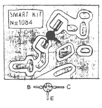
In all cases where Darlington transistors are used because the output devices it is essential that the sensing transistor (Q2) should be in as close thermal contact with the output transistors as potential. thus a TO126-case transistor sort was chosen for straightforward bolting on the heatsink, terribly near the output combine

R30 must be cut so as to live regarding half the voltage supply across the positive lead of C7 and ground. an improved setting is done using an oscilloscope, so as to get a symmetrical clipping of the output wave type at most output power

Note:
To set quiescent current, tide ampare meter in series between supplay with this series, then do the following
  • Set the volume control to the minimum and Trimmer R3 to its minimum resistance.
  • Power-on the circuit and adjust R3 to read a current drawing of about 30 to 35mA.
  • Wait about 15 minutes, watch if the current is varying and readjust if necessary.

List component

R1,R2______________68K 1/4W Resistors
R3________________680K 1/4W Resistor
R4________________220K 1/4W Resistor
R5_________________33K 1/4W Resistor
R6,R16______________2K2 1/4W Resistors
R7__________________5K6 1/4W Resistor
R8,R21____________330R 1/4W Resistors
R9_________________47K 1/4W Resistor
R10_______________470R 1/4W Resistor
R11_________________4K7 1/4W Resistor
R12,R20____________10K 1/4W Resistors
R13_______________100R 1/4W Resistor
R14,R15____________47R 1/4W Resistors
R17,R18,R19_______100K 1/4W Resistors
R22__________________6K8 1W Resistor
R23,R25_____________470R 1/4W Resistors
R24__________________2K 1/2W Trimmer Cermet
R26,R27_______________4K7 1/2W Resistors
R28________________220R 1/2W Resistor
R29__________________2K2 1/2W Resistor
R30_________________50K 1/2W Trimmer Cermet
R31________________68K 1/4W Resistor
R32,R33______________R47 4W Wirewound Resistors


C1,C4,C5,C6________10µF 63V Electrolytic Capacitors
C2_________________47µF 63V Electrolytic Capacitor
C3_________________47pF 63V Ceramic Capacitor
C7_________________15nF 63V Polyester Capacitor
C8_________________22nF 63V Polyester Capacitor
C9________________470nF 63V Polyester Capacitor
C10,C11,C12________10µF 63V Electrolytic Capacitors
C13_______________220µF 63V Electrolytic Capacitor
C14,C15,C17,C18________47µF 63V Electrolytic Capacitors
C16________________100µF 25V Electrolytic Capacitor
C19_________________33pF 63V Ceramic Capacitor
C20_______________1000µF 50V Electrolytic Capacitor

P1,P2______________10K Potentiometers
P3_________________10K Potentiometer

D1,D2____________BAT46 100V 150mA Schottky-barrier Diodes
D3_________________LED

Q1,Q3____________BC546 NPN Transistors
Q2_______________BC556 PNP Transistor
Q4,Q5____________BD139 80V 1.5A NPN Transistors
Q6_____________MJ11016 120V 30A NPN Darlington Transistor
Q7_____________MJ11015 120V 30A PNP Darlington Transistor

J1,J2___________6.3mm. Mono Jack sockets
SW1,SW2___________SPST Switches
SPKR______________speakers 8 or 4 Ohm with Minimum power 75W
Read More..

Tuesday, September 23, 2014

Simple Class A Power Amplifier by IRF530

Simple

I was in need of high quality headphones amplifier because of many reasons and decided to build SDS Labs phone amp. This is extremely rewarding project in a sense that it is fully documented, includes PCB, parts list and building notes – so it’s easy to build and then it sounds great.

I have used IRF530 and IRF9530 pairs and they work just fine given the fact that you add 100-300 Ohm gate resistors to prevent high frequency oscillations. This is a common problem for MOSFET designs and if you don’t have a good oscilloscope or want to be on the safe side just use gate resistors on any MOSFET design. Ferrite beads put over gate pin could also be used instead but I somehow prefer resistors.

Read More..

Monday, September 22, 2014

Class A Power Amplifier by IRF530N 78L05

Class

This is the best design I have came up so far!
I use two 6x6x4cm heatsinks per channel. Power supply is unregulated (just transformer, diode bridge and capacitors) but I cannot hear anything even when I put my ear within few centimeters of the loudspeaker. Opamp has very good power supply rejection ratio. I’ve tried to keep everything as simple as possible and basically LM317 would be just one extra opamp

If you are looking for better sound, get separate regulated low power supply just for the U1 opamp, something like +-15V at 100-200 mA.
I have also used one LM7805 to get bias for both channels – you may want to use two separate 7805 in a final amp to get better channel separation. R2 pot is anything from 500 to 50k. I have used 22k.

Read More..

Sunday, September 21, 2014

Generic Amplifier

    In this blog we talk about audio amplifiers and I would like to get more detail information about them. An audio power amplifier is an electronic amplifier that amplifies low-power audio signals (signals composed primarily of frequencies between 20 - 20 000 Hz, the human range of hearing) to a level suitable for driving loudspeakers and is the final stage in a typical audio playback chain.

     If we talk about the history of amplifiers, we can say, the audio amplifier was invented in 1909 by Lee De Forest when he invented the triode vacuum tube. The triode was a three terminal device with a control grid that can modulate the flow of electrons from the filament to the plate. The triode vacuum amplifier was used to make the first AM radio. Early audio power amplifiers were based on vacuum tubes (also known as valves), and some of these achieved notably high quality (e.g., theWilliamson amplifier of 1947-9). Most modern audio amplifiers are based on solid state devices (transistors such as BJTs, FETs andMOSFETs), but there are still some who prefer tube-based amplifiers, and the valve sound. Audio power amplifiers based on transistors became practical with the wide availability of inexpensive transistors in the late 1960s.

    So, an electronic amplifier, or shortened amp is an electronic device that increases the power of a signal. So if you have a sound from a device and want the sound to be amplified, the amplifier is the device that can help you do this. Numerous types of electronic amplifiers are specialized to various applications. An amplifier can refer to anything from an electrical circuit that uses a single active component, to a complete system such as a packaged audio hi-fi amplifier. 
    Amplifier that any device is characterized by different specifications which actually should be taken when it is designed in consideration of them, and here are some highlights:

Noise
andwidth, 
Gain, 
Efficiency, 
Linearity, 
Output dynamic range, 
Rise time, settling time, ringing and over shoot that characterize the step response
Generic Amplifier
Read More..