Showing posts with label 25. Show all posts
Showing posts with label 25. Show all posts
Saturday, October 25, 2014
25 Watt Audio Amplifier Circuits Diagram
25 Watt Audio Amplifier Circuits Diagram

Parts:
R1,R4_________47K 1/4W Resistors
R2____________4K7 1/4W ResistorR3____________1K5 1/4W ResistorR5__________390R 1/4W ResistorR6__________470R 1/4W ResistorR7___________33K 1/4W ResistorR8__________150K 1/4W ResistorR9___________15K 1/4W ResistorR10__________27R 1/4W ResistorR11_________500R 1/2W Trimmer Cermet
R12,R13,R16__10R 1/4W Resistors
R14,R15_____220R 1/4W Resistors
R17___________8R2 2W ResistorR18____________R22 4W Resistor (wirewound)
C1___________470nF 63V Polyester CapacitorC2___________330pF 63V Polystyrene CapacitorC3,C5________470µF 63V Electrolytic Capacitors
C4,C6,C8,C11_100nF 63V Polyester Capacitors
C7___________100µF 25V Electrolytic CapacitorC9____________10pF 63V Polystyrene CapacitorC10____________1µF 63V Polyester CapacitorQ1-Q5______BC560C 45V 100mA Low noise High gain PNP TransistorsQ6_________BD140 80V 1.5A PNP TransistorQ7_________BD139 80V 1.5A NPN TransistorQ8_________IRF530 100V 14A N-Channel Hexfet Transistor
Q9_________IRF9530 100V 12A P-Channel Hexfet TransistorPower supply circuit diagram

Parts:
R1____________3K3 1/2W Resistor C1___________10nF 1000V Polyester CapacitorC2,C3______4700µF 50V Electrolytic CapacitorsC4,C5_______100nF 63V Polyester Capacitors D1__________200V 8A Diode bridgeD2__________5mm. Red LED F1,F2_______3.15A Fuses with sockets T1__________220V Primary, 25 + 25V Secondary 120VA Mains transformer PL1_________Male Mains plug SW1_________SPST Mains switchNotes:
- Can be directly connected to CD players, tuners and tape recorders. Simply add a 10K Log potentiometer (dual gang for stereo) and a switch to cope with the various sources you need.
- Q6 & Q7 must have a small U-shaped heatsink.
- Q8 & Q9 must be mounted on heatsink.
- Adjust R11 to set quiescent current at 100mA (best measured with an Avo-meter connected in series to Q8 Drain) with no input signal.
- A correct grounding is very important to eliminate hum and ground loops. Connect to the same point the ground sides of R1, R4, R9, C3 to C8. Connect C11 to output ground. Then connect separately the input and output grounds to power supply ground.
- An earlier prototype of this amplifier was recently inspected and tested again after 15 years of use.
Technical data:
Output power:
well in excess of 25 Watt RMS @ 8 Ohm (1KHz sine wave)
Sensitivity:
200mV input for 25W output
Frequency response:
30Hz to 20KHz-1dB
Total harmonic distortion @ 1KHz:
0.1W 0.014% 1W 0.006% 10W 0.006% 20W0.007% 25W 0.01%
Total harmonic distortion @10KHz:
0.1W 0.024% 1W 0.016% 10W 0.02% 20W0.045% 25W 0.07%
Unconditionally stable on capacitive loads
Friday, October 24, 2014
25 Watt Audio Amplifier Circuits Diagram
25 Watt Audio Amplifier Circuits Diagram
Parts:
R1,R4_________47K 1/4W Resistors
R2____________4K7 1/4W ResistorR3____________1K5 1/4W ResistorR5__________390R 1/4W ResistorR6__________470R 1/4W ResistorR7___________33K 1/4W ResistorR8__________150K 1/4W ResistorR9___________15K 1/4W ResistorR10__________27R 1/4W ResistorR11_________500R 1/2W Trimmer Cermet
R12,R13,R16__10R 1/4W Resistors
R14,R15_____220R 1/4W Resistors
R17___________8R2 2W ResistorR18____________R22 4W Resistor (wirewound)
C1___________470nF 63V Polyester CapacitorC2___________330pF 63V Polystyrene CapacitorC3,C5________470µF 63V Electrolytic Capacitors
C4,C6,C8,C11_100nF 63V Polyester Capacitors
C7___________100µF 25V Electrolytic CapacitorC9____________10pF 63V Polystyrene CapacitorC10____________1µF 63V Polyester CapacitorQ1-Q5______BC560C 45V 100mA Low noise High gain PNP TransistorsQ6_________BD140 80V 1.5A PNP TransistorQ7_________BD139 80V 1.5A NPN TransistorQ8_________IRF530 100V 14A N-Channel Hexfet Transistor
Q9_________IRF9530 100V 12A P-Channel Hexfet TransistorPower supply circuit diagram
Parts:
R1____________3K3 1/2W Resistor C1___________10nF 1000V Polyester CapacitorC2,C3______4700µF 50V Electrolytic CapacitorsC4,C5_______100nF 63V Polyester Capacitors D1__________200V 8A Diode bridgeD2__________5mm. Red LED F1,F2_______3.15A Fuses with sockets T1__________220V Primary, 25 + 25V Secondary 120VA Mains transformer PL1_________Male Mains plug SW1_________SPST Mains switchNotes:
- Can be directly connected to CD players, tuners and tape recorders. Simply add a 10K Log potentiometer (dual gang for stereo) and a switch to cope with the various sources you need.
- Q6 & Q7 must have a small U-shaped heatsink.
- Q8 & Q9 must be mounted on heatsink.
- Adjust R11 to set quiescent current at 100mA (best measured with an Avo-meter connected in series to Q8 Drain) with no input signal.
- A correct grounding is very important to eliminate hum and ground loops. Connect to the same point the ground sides of R1, R4, R9, C3 to C8. Connect C11 to output ground. Then connect separately the input and output grounds to power supply ground.
- An earlier prototype of this amplifier was recently inspected and tested again after 15 years of use.
Technical data:
Output power:
well in excess of 25 Watt RMS @ 8 Ohm (1KHz sine wave)
Sensitivity:
200mV input for 25W output
Frequency response:
30Hz to 20KHz-1dB
Total harmonic distortion @ 1KHz:
0.1W 0.014% 1W 0.006% 10W 0.006% 20W0.007% 25W 0.01%
Total harmonic distortion @10KHz:
0.1W 0.024% 1W 0.016% 10W 0.02% 20W0.045% 25W 0.07%
Unconditionally stable on capacitive loads
Tuesday, September 23, 2014
Adjustment power supply values 1 25 15V Max current 0 5 amp circuit
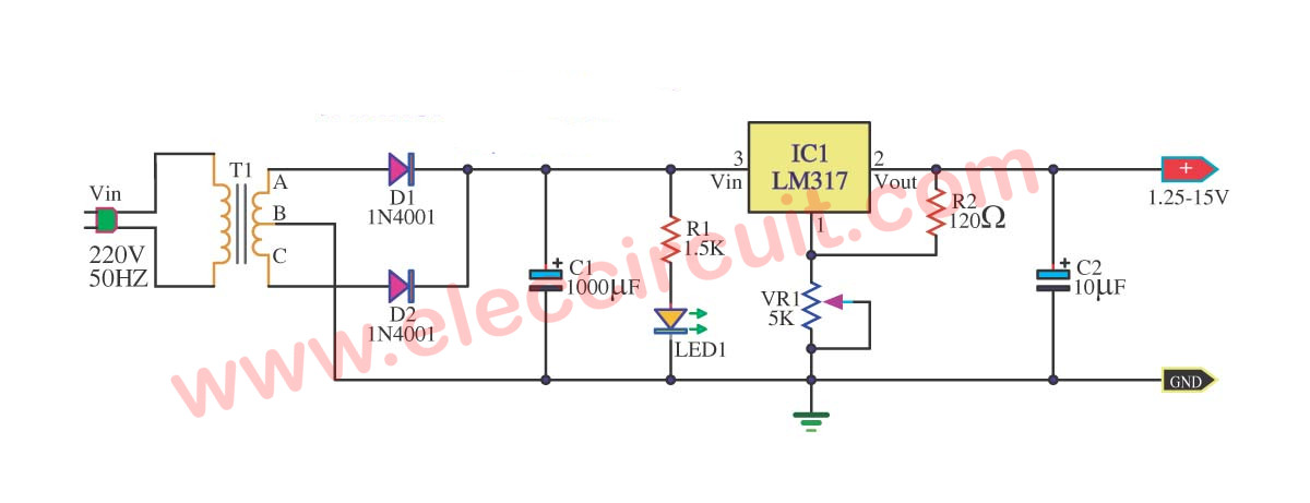
This is power supply that have Voltage output fine the value has 1.25-15V. From by Output current that be valuable about 0.5 amp that 12V and 0.2 amp that 15V.
When Volt , from 220V houses reach transformer. It will modify Volt 220V to be 18VAC already to change rectifier circuit. Which D1, D2, C1 and R1 wasp be Full wave rectifier circuit. For modify DCV to ACV to a signal DCV. It make get a signal DCV that have voltage at pin 3 of IC1 be 20V. From that time DCV signal this reach fight DC Regulator circuit. Which use IC number LM317.
This circuit will perform to maintain one’s position Voltage smoothly. Which level output voltage at get this will go out the way pin 2 of IC1. By have capacitors C2 be voltage filter in order that voltage output level of the circuit is will high class modify to follow fining. The performing fee withstands VR1 there.
from:eleccircuit.com
Wednesday, September 17, 2014
4 × 25 W BTL quad car radio power amplifier
General Description
The TDA8568Q is a integrated class-B output amplifier in a 23-lead Single-In-Line (SIL) plastic power package. It contains four amplifiers in BTL configuration, each with a gain of 40 dB. The output power is 4 × 25 W in a 4 Ω load.
Circuit Diagram
 |
| 4 × 25 W BTL quad car radio power amplifier |
Friday, August 29, 2014
25 W Audio Power Amplifier Wiring diagram Schematic
This audio power amplifier project is based on LM1875 amplifier module from National Semiconductor. It can deliver up to 30W of power using an 8 ohm load & dual 30V DC power supplies. It is designed to operate with maximum outside parts with current limit & thermal shutdown protection features . Other features include high gain, quick slew rate, wide power supply range, giant output voltage swing & high current capability.
Summary of the audio amply-fire features:
Summary of the audio amply-fire features:
- Low distortion: 0.015%, 1 kHz, 20 W
- Wide power bandwidth: 70 kHz
- Wide supply range 16V-60V
- Up to 30 watts output power
- Internal output protection diodes
- Protection for AC & DC short diagram to ground
- 94 dB ripple rejection
- Plastic power package TO-220
25V Power Supply
The schematic below shows how the +25V DC & -25V DC are obtained. In order to provide power supply for two stereo amplifiers, a power transformer rating of 80VA with 240V/36V middle tapped secondary winding is used. The secondary output of the transformer is rectified by using 1N5401 diodes together with four electrolytic capacitors to smoother the ripple voltage. A fuse & a varistor are connected at the primary input to protect the schema against power surge.
25-W Audio Power Amplifier Circuit Diagram
Audio Amplifier Module
The +25V & -25V DC power supply are connected to the audio amplifier module through a 2A fuse with the peripheral devices shown in the schematic below. The audio input signal to be amplified is coupled to pin one of LM1875 through the resistor R1 and electrolytic capacitor E5.
The +25V & -25V DC power supply are connected to the audio amplifier module through a 2A fuse with the peripheral devices shown in the schematic below. The audio input signal to be amplified is coupled to pin one of LM1875 through the resistor R1 and electrolytic capacitor E5.
The output signal at pin four of LM1875 can be used to directly drive a 8 ohm loudspeaker. Resistor R6 and capacitor C5 prevent-the capacitance developed at the long speaker leads from driving the amplifier in to High Frequency Oscillation.
A heat-sink with a thermal resistance rating of one.4 Cecilius/Watt or better must be used or else the amplifier module will-be cut-off from operation due to the heat that will build up in the coursework of the operation of the amplifier. Take note that the heat sink tab on the IC module is internally connected to the -25V power supply hence it must be isolated from the heat sink by the use of an insulating washer. If this is not done, the negative rail will be shorted to ground.
A heat-sink with a thermal resistance rating of one.4 Cecilius/Watt or better must be used or else the amplifier module will-be cut-off from operation due to the heat that will build up in the coursework of the operation of the amplifier. Take note that the heat sink tab on the IC module is internally connected to the -25V power supply hence it must be isolated from the heat sink by the use of an insulating washer. If this is not done, the negative rail will be shorted to ground.
Subscribe to:
Posts (Atom)