Showing posts with label light. Show all posts
Showing posts with label light. Show all posts
Monday, November 3, 2014
FLASH LIGHT ELECTRONIC DIAGRAM
FLASH LIGHT ELECTRONIC DIAGRAM
IC NE555 works as an astable multivibrator with variation on the frequency. With this circuit, the LED blinks every half second. How long the blink time is, can be adjusted by adjusting the value of capacitor C1. Up to 18 additional LEDs can be attached to this circuit (36 LEDs total).
Components :
Diode D1-D2 : 5mm LED
Resistor R1 : 4K7 ohm
Resistor R2 : 1k ohm
Resistor R3-R4 : 330 ohm
Variable resistor VR1 : 100k ohm
Polar capacitor C1 : 10 uF/10 V
Capacitor C2 : 0.01 uF
IC1 : NE555
6V power supply
Saturday, October 25, 2014
Build a Solar Garden Light Circuit Diagram
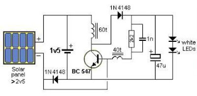
This is a Solar Garden Light Circuit Diagram that consists of a very simple system garden lighting that can be done by using some common electronic parts and a small solar panel. The electronic design is simple yet very efficient, has the advantage of being solar powered, it requires only one transistor, one 2.5 volt solar panel and some other common electronic components you can remove junk.
This solar lighting system automatically turns on the LEDs when the solar panel detects no light turns off when the solar panel produces more than 1v and charges the battery when the panel produces more than 2.1V
The coils in this circuit require a core material F29 and they must be made with wire of 0.095 mm in core 2.6x6mm. "This circuit uses the system joule thief (joule thief) to provide voltage necessary for the LED, so other coils can be tested.
The coils in this circuit require a core material F29 and they must be made with wire of 0.095 mm in core 2.6x6mm. "This circuit uses the system joule thief (joule thief) to provide voltage necessary for the LED, so other coils can be tested.
Solar Garden Light Circuit Diagram

Monday, October 20, 2014
Automatic Low Power Emergancy Light Circuit diagram
Here is a white-LED-based emergency light that offers the following advantages. 1-It is highly bright due to the use of white LEDs. 2-The light turns on automatically when mains supply fails, and turns off when mains power resumes. 3-It has its own battery charger. When the battery is fully charged, charging stops automatically. The charger power supply section is built around 3-terminal adjustable regulator IC LM317 (IC1), while the LED driver section is built around transistor BD140 (Q2).
In the charger power supply section, an input AC main is stepped down by T1 to deliver 9V, 500mA to the bridge rectifier, which comprises diodes D1 through D4. Filter capacitor C1 eliminates ripples. Unregulated DC voltage is fed to input pin 3 of IC1 and provides charging current through D5 and limiting resistor R15. By adjusting preset P1, the output voltage can be adjusted to deliver the required charging current. When the battery gets charged to 6.8V, D6 conducts and charging current from IC1 finds a path throughQT1 to ground and it stops charging of the battery. When mains power is available, the base of Q2 remains high and Q2 does not conduct. Thus LEDs are off.
On the other hand, when mains fails, the base of Q2 becomes low and it conducts. This makes all the LEDs glow. The mains power supply, when available, charges the battery and keeps the LEDs off as Q2 remains cut-off. During mains failure, the charging section stops working and the B1 supply makes the LEDs glow. Assemble the circuit on a general-purpose PCB and enclose in a cabinet with enough space for battery and switches. We have tested the circuit with twelve 10mm white LEDs. You can use more LEDs provided the total current consumption does not exceed 1.5A. Driver transistor Q2 can deliver up to 1.5A with proper heat-sink arrangement.
Circuit diagram:
Fully Automatic Emergency Light Circuit Diagram
Parts:
P1 = 2.2K
R1-R12 = 100R-1/2W
R13 = 1K-1/2W
R14 = 180R-1/2W
R15 = 16R/5W
R16 = 1.2K
C1 = 1000uF-25V
D1-D5 = 1N4007
D6 = 6.8V-0.5W Zener
D7-D18 = 10mm- White LEDs
Q1 = BC548
Q2 = BD140
B1 = 6V-4.5Ah Battery
IC1 = LM317
T1 = 9Vac-Transformer
P1 = 2.2K
R1-R12 = 100R-1/2W
R13 = 1K-1/2W
R14 = 180R-1/2W
R15 = 16R/5W
R16 = 1.2K
C1 = 1000uF-25V
D1-D5 = 1N4007
D6 = 6.8V-0.5W Zener
D7-D18 = 10mm- White LEDs
Q1 = BC548
Q2 = BD140
B1 = 6V-4.5Ah Battery
IC1 = LM317
T1 = 9Vac-Transformer
Saturday, October 18, 2014
Indicator light using Windows Comparison Circuit Diagram
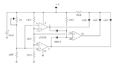
This circuit indicator light level using operational amplifier, LDR and indiction is by LEDs. There are a variety of LDR, its resistance varies from less than 100 ohms on a cloudy day in more than one megohm in complete darkness. A trimmer 2K was used to adjust the range of comparison. This configuration can also be used to indicate the reconnoiter.
Indicator light using Windows Comparison Circuit Diagram

Wednesday, October 1, 2014
Light Activated Switch Circuit Using IC 555
A very useful light activated switch circuit can be made by utilising a single 555 timer with its trigger and threshold inputs connected together.
The schmitt has a very low input current (1.5uA) and can directly drive a relay taking up to 200mA of current. The circuit shows a 555 schmitt being used to energise a relay when the light level on a photoconductive cell falls below a preset value; the relay energises when the voltage on pins 2 and 5 is greater than 2/3Vcc and de-energises when the voltage falls below I/3Vcc. This gives a hysteresis of 1/3Vcc, The circuit can be used in many other similar applications where a high input impedance and low out- put impedance are required with the minimum component count.

The schmitt has a very low input current (1.5uA) and can directly drive a relay taking up to 200mA of current. The circuit shows a 555 schmitt being used to energise a relay when the light level on a photoconductive cell falls below a preset value; the relay energises when the voltage on pins 2 and 5 is greater than 2/3Vcc and de-energises when the voltage falls below I/3Vcc. This gives a hysteresis of 1/3Vcc, The circuit can be used in many other similar applications where a high input impedance and low out- put impedance are required with the minimum component count.

Saturday, September 13, 2014
Fluorescent Tube Light Driver Wiring diagram Schematic 10W

This is very useful schema for us.Because we can light up 10W Fluorescent lamp by using this schema diagram.This schema operates with single transformer.I suppose now you can enjoy this inverter.When you wind the transformer do it carefully because that is the heart of this schema.

Note
# Be careful when you operate this schema because high voltage is dangerous.
# This schema is not good for kids
Thursday, September 11, 2014
Light Flasher
 This is a very basic schema for flashing one or more LEDS and also to alternately flash one or more LEDs.
It uses a 555 timer setup as an astable multivibrator with a variable frequency.

With the preset at its max. the flashing rate of the LED is about 1/2 a second. It can be increased by increasing the value of the capacitor from 10uF to a higher value. For example if it is increased to 22uF the flashing rate becomes 1 second.
There is also provision to convert it into an alternating flasher. You just have to connect a LED and a 330ohm as shown in Fig.2 to the points X and Y of Fig.1. Then both the LEDs flash alternately.
Since the 555 can supply or sink in upto 200mA of current, you can connect upto about 18 LEDS in parallel both for the flasher and alternating flasher (that makes a total of 36 LEDs for alternating flasher).
Saturday, September 6, 2014
Simple Light Switch

Tuesday, September 2, 2014
Light dimmer circuit AC 120W

This is Ac light dimmer schema diagram.You can use bulbs up to 120W.Here You can use common VR.Triac should have heat sink.

Note
# Dont pass 120W.
# This is not good for kids because this is 230Ac schema.
Tuesday, August 26, 2014
12V Police Flashing Light Circuit


Note:
# Dont supply over 15V
# Build this schema on a PCB
# In some countries this schema is illegal.we give you this with the educational purpose.We dont get any responsibility of misusing this schema
Subscribe to:
Posts (Atom)
