Showing posts with label indicator. Show all posts

Saturday, October 25, 2014

Simple Indicator for Dynamic Limiter Schematic Diagram

The indicator described here is specifically designed for adjusting the dynamic limiter described elsewhere in this edition and checking whether the maximum level of the reference voltage (P1) needs to be modified. Her e we use a 4 -to -16 decoder IC (type 4514) to monitor the state of the four-bit up/down counter in the limiter circuit. This IC can be powered from the ±8 V supply voltages of the limiter. The limiter board has a 6-way connector (K5) that provides access to the four counter outputs and the sup-ply voltages. Connector K1 of the indicator circuit can be connected to K5 on the limiter board.
 Indicator for Dynamic Limiter Schematic

One output of the 4514 goes high for each unique 4-bit combination on its inputs, while the other outputs remain logic Low. A separate current-limiting resistor is connected in series with each LED. It was not possible to use a common cathode resistor here because most LEDs have a maximum reverse blocking voltage of only 5 V, while the supply voltage here (16 V) is a good deal higher.

The 16 LEDs ar ranged in a r ow pr ov ide a ‘fluid’ indication of the control process. You can enhance the display by using different colours for the first and last LEDs, such as red for D1 (maximum gain) and green for D16 (minimum gain), with yellow for the rest of the LEDs. While observing signals from various sources (TV set, DVD, media player, etc.), you can easily use the 16 LEDS to monitor the behaviour of the limiter and adjust the setting of potentiometer P1 in the limiter circuit. It must be set such that D16 only lights up at the maximum signal level. If this is not possible and D16 remains lit a good deal of the time regardless of the position of P1, it will be necessar y to increase the value of P1. Of course, it is also poss-ible to adjust P1 so the strongest signal source extends slightly above the control range of the limiter.

This circuit can easily be assembled on a small piece of prototyping board. The current consumption is around 4 mA. link
Read More..

Thursday, October 23, 2014

Audio Peak Indicator Circuit

The existence of the peak indicator "Audio Peak Indicator" in an audio device is needed. Audio Peak indicator is a simple circuit to detect the peak level of audio signal. Audio Peak indicator circuit is built with duabuah transistor and LED indicator as peak level detection of audio signals.

The main function of a series of Audio Peak indicator is to determine the occurrence of the peak level of audio signal that is more than +4 dB, equivalent to 1.25 V rms. If the received audio signal Audio Peak Indicator more than +4 dB was the LEDs in series Peak Audio This indicator will light. Audio Peak indicator circuit is mounted on the output audio system.
Audio Peak Indicator Component List:
R1 = 10Kohm
R2 = 1.2Kohm
R3 = 220Kohm
R4-5 = 4.7Kohm
C1 = 47uF 25V
C2 = 2.2uF 25V
Q1-2 = BC550C
D1 = LED RED

We hope to form the reference materials in the manufacture of circuit pernagkat Audio Peak Indicators in the audio readers.
Read More..

Saturday, October 18, 2014

Indicator light using Windows Comparison Circuit Diagram

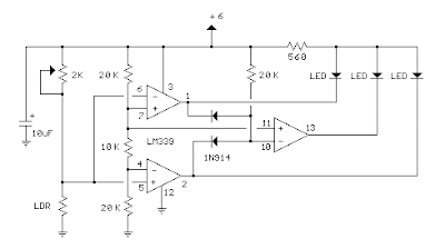
This circuit indicator light level using operational amplifier, LDR and indiction is by LEDs. There are a variety of LDR, its resistance varies from less than 100 ohms on a cloudy day in more than one megohm in complete darkness. A trimmer 2K was used to adjust the range of comparison. This configuration can also be used to indicate  the reconnoiter.
 
 Indicator light using Windows Comparison Circuit Diagram
 
Indicator light using Windows Comparison Circuit Diagram
 
Read More..

Wednesday, October 15, 2014

Simple Stereo Indicator Detects L R Signal Difference

This true stereo indicator is different from what we usually find on FM radio receiver, which is usually a pilot tone detector. A stereo broadcast from FM radio station contain pilot tone, but a presence of pilot tone doesn’t necessarily a stereo broadcast signal since a mono FM transmitter ca broadcast pilot tone as well.  Since this circuit detect the difference between left and right channel, this circuit can detect a real stereophonic programs. 

When there is no difference between R and L input signals, the output A1 and output A2 is at the same potential. That will make a a virtual ground rail at half the supply voltage. Here is the schematic diagram of the circuit. The A1 will supply a negative or positive voltage when A1 detects a difference between R and L input signals with respect to the virtual ground rail. 

The C4 will be charged via D2 an C3 via D1. The LED is turned on by the comparator A3/A4 via OR circuit D3/D4. The input signal level should be greater than 100mV to compensate for the drop across D2 or D1. P1 is used to adjust the sensitivity of stereo indicator.

 Stereo Indicator Detects L-R Signal Difference Circuit Diagram


Read More..

Friday, September 19, 2014

Fastest Finger First Indicator

Quiz-type game shows are increasingly becoming popular on tale vision these days. In such games, fastest finger first indicators (FFFIs) are used to test the player’s reaction time. The player’s designated number is dis played with an audio alarm when the player presses his entry button. The circuit presented here determines as to which of the four contestants first pressed the button and locks out the remaining three entries. Simultaneously, an audio alarm and the correct decimal number display of the corresponding contestant are activated. 

Circuit Diagram:
Fastest Finger First Indicator Circuit-Diagram
Fastest Finger First Indicator Circuit Diagram
 
When a contestant presses his switch, the corresponding output of latch IC2 (7475) changes its logic state from 1 to 0. The combinational circuitry comprising dual 4-input NAND gates of IC3 (7420) locks out subsequent entries by producing the appropriate latch-disable signal. Priority encoder IC4 (74147) encodes the active-low input condition into the cor responding binary coded decimal (BCD) number output. The outputs of IC4 after inversion by inverter gates inside hex inverter 74LS04 (IC5) are coupled to BCD-to-7-segment decoder/display driver IC6 (7447). The output of IC6 drives common-anode 7-segment LED display (DIS.1, FND507 or LT543). 

The audio alarm generator comprises clock oscillator IC7 (555), whose output drives a loudspeaker. The oscillator frequency can be varied with the help of preset VR1. Logic 0 state at one of the outputs of IC2 produces logic 1 input condition at pin 4 of IC7, thereby enabling the audio oscillator.  IC7 needs +12V DC supply for sufficient alarm level. The remaining circuit operates on regulated +5V DC supply, which is obtained using IC1 (7805). Once the organiser identifies the contestant who pressed the switch first, he disables the audio alarm and at the same time forces the digital display to ‘0’ by pressing reset pushbutton S5. With a slight modification, this circuit can accommodate more than four contestants. 


Author : P. Rajesh Bhat  – Copyright : EFY
Read More..

Thursday, September 11, 2014

Mobile incoming call indicator


This schema can be used to escape from the nuissance of obile phone rings when you are at home.This schema will give a visual indication if placed near a mobile phone even if the ringer is deactivated.


When a call is coming to the mobile phone, the transmitter inside it becomes activated.The frequency of the transmitter is around 900MHz.The coil L1 picks up these oscillations by induction and feds it to the base of Q1.This makes the transistor Q1 activated.Since the Collector of Q1 is connected to the pin 2 of IC1 (NE555) , the IC1 is triggered to make the LED connected at its output pin (pin 3) to blink.The blinking of the LED is the indication of incoming call.


Notes.

* The coil L1 can be made by making 150 turns of 36 SWG enameled copper wire on a 5mm dia plastic former.Or you can purchase a 10 uH coil from shop if available.
* The schema can be powered from a 6V battery.
* Assemble the schema on a good quality PCB.
* C1 & C3 are to be polyester capacitors.
* The electrolytic capacitor C2 must be rated 10V.

Read More..

Tuesday, September 2, 2014

Audio Peak Indicator Circuit

The existence of the peak indicator "Audio Peak Indicator" in an audio device is needed. Audio Peak indicator is a simple circuit to detect the peak level of audio signal. Audio Peak indicator circuit is built with duabuah transistor and LED indicator as peak level detection of audio signals.


The main function of a series of Audio Peak indicator is to determine the occurrence of the peak level of audio signal that is more than +4 dB, equivalent to 1.25 V rms. If the received audio signal Audio Peak Indicator more than +4 dB was the LEDs in series Peak Audio This indicator will light. Audio Peak indicator circuit is mounted on the output audio system.
Audio Peak Indicator Component List:
R1 = 10Kohm
R2 = 1.2Kohm
R3 = 220Kohm
R4-5 = 4.7Kohm
C1 = 47uF 25V
C2 = 2.2uF 25V
Q1-2 = BC550C
D1 = LED RED

We hope to form the reference materials in the manufacture of circuit pernagkat Audio Peak Indicators in the audio readers.
Read More..

Friday, August 29, 2014

Audio Clipping Indicator

Detects clipping in preamp stages, mixers, amplifiers etc., Single LED display - 9V Battery supply unit
This schema was intended to be used as a separate, portable unit, to signal by means of a LED when the output wave form of a particular audio stage is "clipping" i.e. is reaching the onset of its maximum permitted peak-to-peak voltage value before an overload is occurring. This will help the operator in preventing severe, audible distortion to be generated through the audio equipment chain. 

This unit is particularly useful in signaling overload of the input stages in mixers, PA or musical instruments amplification chains, but is also suited to power amplifiers. A careful setting of Trimmer R5 will allow triggering of the LED with a wide range of peak-to-peak input voltages, in order to suit different requirements. Unfortunately, an oscilloscope and a sine wave frequency generator are required to accurately setup this schema. Obviously, the unit can be embedded into an existing mixer, preamp or power amplifier, and powered by the internal supply rails in the 9 - 30V range. The power supply can also be obtained from higher voltage rails provided suitable R/C cells are inserted. SW1 and B1 must obviously be omitted.


Audio_Clipping_Indicator_Circuit
Audio Clipping Indicator Circuit Diagram


Parts:
R1___________1M 1/4W Resistor (See Notes)
R2,R3,R8_____100K 1/4W Resistors
R4,R6________10K 1/4W Resistors
R5___________5K 1/2W Trimmer Cermet or Carbon
R7___________2K2 1/4W Resistor
R9___________22K 1/4W Resistor
R10__________1K 1/4W Resistor (See Notes)
C1,C4________220nF 63V Polyester Capacitors
C2___________4p7 63V Ceramic Capacitor (See Notes)
C3___________220µF 25V Electrolytic Capacitor
C5___________10µF 25V Electrolytic Capacitor (See Notes)
D1,D2________1N4148 75V 150mA Diodes
D3___________LED (Any dimension, shape and color)
Q1___________BC547 45V 100mA NPN Transistor
IC1___________TL062 Dual Low current BIFET Op-Amp (or TL072, TL082)
SW1__________SPST Toggle or Slide Switch (See Text)
B1____________9V PP3 Battery (See Text)

Circuit operation:
The heart of the schema is a window comparator formed by two op-amps packaged into IC1. This technique allows to detect precisely and symmetrically either the positive or negative peak value reached by the monitored signal. The op-amps outputs are mixed by D1 and D2, smoothed by C4, R7 and R8, and feed the LED driver Q1 with a positive pulse. C5 adds a small output delay in order to allow detection of very short peaks.

Notes:
  • With the values shown, the schema can be easily set up to detect sine wave clipping from less than 1V to 30V peak-to-peak (i.e. 15W into 8 Ohms). If you need to detect higher output peak-to-peak voltages, R1 value must be raised. On the contrary, if the schema will be used to detect only very low peak-to-peak voltages, it is convenient to lower R1 value to, say, 220K omitting C2. In this way, the adjustment of R5 will be made easier.
  • Using a TL062 chip at 9V supply, stand-by current drawing is about 1.5mA and less than 10mA when the LED illuminates. With TL072 or TL082 chips, current drawing is about 4.5mA and 13mA respectively.
  • When using power supplies higher than 12V, the value of R10 must be raised accordingly.
  • When using power supplies higher than 25V, the working voltage value of C5 must be raised to 35 or 50V.
Read More..

Wednesday, August 27, 2014

Audio Power Indicator

This is audio level indicator which can be used to measure the audio level output of your amplifier. Simply connect the output of your amplifier to the input of this schema, then you will know the average value of your amplifiers power.
Audio

R1_____________220R 1/2W Resistor
R2,R5,R6,R8____100R 1/4W Resistors
R10,R12,R14____100R 1/4W Resistors
R3_____________220R 1/4W Resistor
R4,R7__________330R 1/2W Resistors
R9_____________560R 1/2W Resistor
R11____________820R 1/2W Resistor
R13______________1K2 1/2W Resistor

D1___________1N4004 400V 1A Diode
D2,D4,D6__BZX79C2V7 2.7V 500mW Zener Diodes
D3,D5,D7,D8,D9,D10 Red LEDs (Any dimension and shape) (See Notes)

Notes:

  • The output power indicated by each LED must be doubled when 4 Ohms loads are driven.
  • The schema can be adapted to suit less powerful amplifiers by reducing the number of LEDs and related voltage dividers.
  • LEDs of any dimension can be used, but rectangular shaped devices will be more suitable to be compacted in bars or columns.
  • For a stereo amplifier, two identical diagram are required.

Read More..