Wednesday, November 5, 2014
Portable Microphone Preamplifier
This circuit is mainly intended to provide common home stereo amplifiers with a microphone input. The battery supply is a good compromise: in this manner the input circuit is free from mains low frequency hum pick-up and connection to the amplifier is more simple, due to the absence of mains cable and power supply. Using a stereo microphone the circuit must be doubled. In this case, two separate level controls are better than a dual-ganged stereo potentiometer. Low current drawing (about 2mA) ensures a long battery life.
Circuit Operation:
The circuit is based on a low noise, high gain two stage PNP and NPN transistor amplifier, using DC negative feedback through R6 to stabilize the working conditions quite precisely. Output level is attenuated by P1 but, at the same time, the stage gain is lowered due to the increased value of R5. This unusual connection of P1, helps in obtaining a high headroom input, allowing to cope with a wide range of input sources (0.2 to 200mV RMS for 1V RMS output).
Portable Microphone Preamplifier Circuit diagram:
P1 = 2.2K
R1 = 100K
R2 = 100K
R3 = 100K
R4 = 8.2K
R5 = 68R
R6 = 6.8K
R7 = 1K
R8 = 1K
R9 = 150R
C1 = 1uF-63V
C2 = 100uF-25V
C3 = 100uF-25V
C4 = 100uF-25V
C5 = 22uF-25V
Q1 = BC560
Q2 = BC550
Notes:
- Harmonic distortion is about 0.1% @ 1V RMS output (all frequencies).
- Maximum input voltage (level control cursor set at maximum) = 25mV RMS
- Maximum input voltage (level control cursor set at center position) = 200mV RMS
- Enclosing the circuit in a metal case is highly recommended.
- Simply connect the output of this device to the Aux input of your amplifier through screened cable and suitable connectors.
4 X 15 Watt Mini Power Amplifier
A lot of electronic circuits in the domain of audio amplifiers are already been published here. This circuit is a little different because it is a four channel amplifier. Each channel of this amplifier can deliver an output of 15Watts into a 4 ohm speaker. The amplifier can be operated from a single 12V DC supply and this makes it possible to use this amplifier in car audio applications too.
4 X 15 Watt Mini Power Amplifier Circuit Diagram :
![4X15W-amplifier-circuit]()
The circuit is based on the 15W BTL X 2 channel audio power amplifier IC TA8215 from Toshiba. Even though chip is specifically designed for car audio applications it can be also used for home audio applications. Two TA8215 ICs are used here in order to obtain a 4 channel amplifier system. The circuit is designed almost exactly as per the application diagram in the ICs datasheet. Pins 7 and 19 are the Vcc pins of the ICs internal integrated power amplifier stages and these pins are connected to the positive supply. Pin 9 is the Vcc pin for ICs internal preamplifier and it is also connected to the positive supply. Pins 13 and 14 are the internal power amplifiers ground pins and they are tied together and connected to the ground.
The internal preamplifier’s ground pin (pin5) is connected to the common ground through a 10 Ohm resistor which makes the input ground separated from the common ground by a resistance of 10 ohms and this improves the noise rejection. The 100uF capacitor works as a power supply de-coupler. The resistor networks connected to the output lines of each amplifier improves the high frequency stability. The variable resistors (R3, R4, R12 and R13) works as the volume controller for the corresponding channels.
Notes :
4 X 15 Watt Mini Power Amplifier Circuit Diagram :
The internal preamplifier’s ground pin (pin5) is connected to the common ground through a 10 Ohm resistor which makes the input ground separated from the common ground by a resistance of 10 ohms and this improves the noise rejection. The 100uF capacitor works as a power supply de-coupler. The resistor networks connected to the output lines of each amplifier improves the high frequency stability. The variable resistors (R3, R4, R12 and R13) works as the volume controller for the corresponding channels.
Notes :
- Assembling the circuit on a good quality PCB is a must for obtaining optimum sound quality.
- Use 12V DC for powering the circuit.
- The ICs must be fitted with adequately sized heat sinks.
- R3, R4, R12 and R13 serves as volume controllers.
- K1 to K4 can be 4 Ohm, 20W speakers.
- This amplifier circuit can be used in a variety of applications such as car audio systems, home theater systems, personal audio systems, public address systems etc.
Tuesday, November 4, 2014
Stereo Power Amplifier Circuit based on BA5417
BA5417 is a stereo amplifier IC with a lot of good features like thermal shut down, standby function, soft clipping, wide operating voltage range etc. The IC can deliver 5W per channel into 4 ohm loud speakers at 12V DC supply voltage. The BA5417 has excellent sound quality and low THD (total harmonic distortion) around 0.1% at F=1kHz; Pout=0.5W.
Stereo Power Amplifier Circuit diagram :
Setup and working of this stereo power amplifier circuit is somewhat similar to the BA5406 based stereo amplifier circuit published previously. C10 and C11 are DC decoupling capacitors which block any DC level present in the input signals. C2 and C6 couples the amplifiers left and right power outputs to the corresponding loud speakers. C1 and C5 are bootstrap capacitors.
Bootstrapping is a method in which a portion of the amplifiers is taken and applied to the input. The prime objective of bootstrapping is to improve the input impedance. Networks R1,C3 and R2,C7 are meant for improving the high frequency stability of the circuit. C4 is the power supply filter capacitor. S1 is the standby switch. C8 is a filter capacitor. R3 and R4 sets the gain of the left and right channels of the amplifier in conjunction with the 39K internal feedback resistors.
Note :
- Supply voltage range of BA5417 is from 6 to 15V DC.
- The recommended supply voltage for this circuit is 12V DC.
- The power supply must be well regulated and filtered.
- BA5417 requires a heatsink.
- The circuit can be assembled on a perf board without much degradation in performance.
UHF antenna booster circuit diagram
UHF Antenna BoosterUHF antenna booster can be used for better reception, especially when you’re far from TV station / relay transmitter. This UHF antenna booster works in 400-850 MHz range. Here is the circuit diagram of the UHF antenna booster: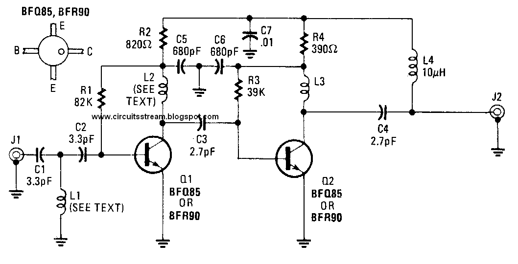
Read More..
The circuit use only one transistor, but it gives you 10 to 15 dB amplification, enough for many situation. The most important part is that the transistor circuitry should be shielded from the input circuitry, as shown in the schematic diagram by the dashed line. This ircuit is powered via the signal cable, since the antenna booster circuit must be wired as close as possible to the antenna. This is very important since the amplifier should amplify the signal acquired by the antenna, not the noise picked by the cable from the antenna to the circuit. The antenna and the booster circuit can be installed above your house’s roof. Long 75 ohm coaxial cable can be drawn from the this booster circuit output to the power supply unit close to TV set.
Just insert a 50-10o uH inductor or RF choke between the output cable and the power supply. Tap the output signal from the output cable using a small 100pF ceramic capacitor to block the DC voltage from the power supply. Adjust P1 to get the best reception, and this should set the working current consumption to around 5-15 mA.
Monday, November 3, 2014
Versatile Micropower Battery Protector
Protect your expensive batteries from discharge damage with this mini-sized electronic cutout switch. It uses virtually no power and can be built to suit a wide range of battery voltages.
Main Features

![versatile-micropower-battery-protector-circuit-backside]()
Back in May 2002, we (Silicon Chip) presented the "Battery Guardian", a project designed specifically for protecting 12V car batteries from over-discharge. This unit has proven to be very popular and is still available from kit suppliers. This new design does not supersede the Battery Guardian – at least not when it comes to 12V car batteries. Instead, it’s a more flexible alternative that can be used with a wide range of battery voltages.
Parts layout:
![front-parts-layout-versatile-micropower-battery-protector-circuit]()
![back-parts-layout-versatile-micropower-battery-protector-circuit]()
In this new "Micropower Battery Protector", we’ve dispensed with the low-battery warning circuitry and the relatively cheap N-channel MOSFET used in the Battery Guardian in favour of a physically smaller module that steals much less battery power. It costs a little more but can switch lower voltages, allowing it to be used with 6V & 12V lead-acid batteries and 4-cell to 10-cell NiCd and NiMH battery packs.
![pcb-layout-versatile-micropower-battery-protector-circuit]()
Most battery-powered equipment provides no mechanism for disconnecting the batteries when they’re exhausted. Even when the voltage drops too low for normal operation, battery drain usually continues until all available energy is expended. This is particularly true of equipment designed to be powered from alkaline or carbon cells but retro-fitted with rechargeables.
Circuit diagram:
![versatile-micropower-battery-protector-circuit-diagram]()
Another example is emergency lighting and security equipment designed to be float-charged from the mains. In an extended blackout period, the batteries can be completely drained and may not recover when the mains power is finally restored.
Main Features
- Disconnects load at preset battery voltage
- Automatically reconnects load when battery recharged
- Ultra-low power consumption (<20ma)
- Miniature size
- 10A maximum rating
- Suitable for use with 4.8-12.5V batteries
- Transient voltage protection (optional)
- Cars, boats & caravans
- Security systems
- Emergency lighting
- Small solar installations
- Camera battery packs
- Many other low-power applications

Back in May 2002, we (Silicon Chip) presented the "Battery Guardian", a project designed specifically for protecting 12V car batteries from over-discharge. This unit has proven to be very popular and is still available from kit suppliers. This new design does not supersede the Battery Guardian – at least not when it comes to 12V car batteries. Instead, it’s a more flexible alternative that can be used with a wide range of battery voltages.
In this new "Micropower Battery Protector", we’ve dispensed with the low-battery warning circuitry and the relatively cheap N-channel MOSFET used in the Battery Guardian in favour of a physically smaller module that steals much less battery power. It costs a little more but can switch lower voltages, allowing it to be used with 6V & 12V lead-acid batteries and 4-cell to 10-cell NiCd and NiMH battery packs.
PCB layout:
Most battery-powered equipment provides no mechanism for disconnecting the batteries when they’re exhausted. Even when the voltage drops too low for normal operation, battery drain usually continues until all available energy is expended. This is particularly true of equipment designed to be powered from alkaline or carbon cells but retro-fitted with rechargeables.
Circuit diagram:
Another example is emergency lighting and security equipment designed to be float-charged from the mains. In an extended blackout period, the batteries can be completely drained and may not recover when the mains power is finally restored.
FLASH LIGHT ELECTRONIC DIAGRAM

FLASH LIGHT ELECTRONIC DIAGRAM
IC NE555 works as an astable multivibrator with variation on the frequency. With this circuit, the LED blinks every half second. How long the blink time is, can be adjusted by adjusting the value of capacitor C1. Up to 18 additional LEDs can be attached to this circuit (36 LEDs total).
Components :
Diode D1-D2 : 5mm LED
Resistor R1 : 4K7 ohm
Resistor R2 : 1k ohm
Resistor R3-R4 : 330 ohm
Variable resistor VR1 : 100k ohm
Polar capacitor C1 : 10 uF/10 V
Capacitor C2 : 0.01 uF
IC1 : NE555
6V power supply
Sunday, November 2, 2014
tda4605 datasheet
tda4605
CONTROL CIRCUIT FOR SWITCH MODE POWER SUPPLIES USING MOS TRANSISTORS

The IC TDA4605controls the MOS PowerTransistor and performs all necessary regulation and
monitoring functions in free running flyback converters.
Since good load regulation over a wide load range is attained, this IC is particularly suitable
for Consumer as well asIndustrial PowerSupplies.
Alternative source of theTDA4605 is alsoavail-
ablefrom SIEMENS semiconductors Consumer ElectronicsA.G.
IRF740 Datasheet power MOSFET
N - CHANNEL 400V - 0.48 Ω - 10 A - TO-220
PowerMESH MOSFET
This power MOSFET is designed using the company’s consolidated strip layout-based MESH OVERLAY process. This technology matches and improves the performances compared with standard parts from various sources.
APPLICATIONS
# HIGH CURRENT SWITCHING
# UNINTERRUPTIBLE POWER SUPPLY (UPS
# DC/DC COVERTERS FOR TELECOM,
# INDUSTRIAL, AND LIGHTING EQUIPMENT

MOSFET, N, 400V, 10A, TO-220; Transistor Type:MOSFET; Transistor Polarity:N; Voltage, Vds Typ:400V; Current, Id Cont:10A; Resistance, Rds On:0.55ohm; Voltage, Vgs Rds on Measurement:10V; Voltage, Vgs th Typ:4V; Case Style:TO-220AB; Termination Type:Through Hole; Current, Idm Pulse:40A; Power Dissipation:125W; Power, Pd:125W; Thermal Resistance, Junction to Case A:1 C/W; Voltage, Vds Max:400V
Read More..
PowerMESH MOSFET
This power MOSFET is designed using the company’s consolidated strip layout-based MESH OVERLAY process. This technology matches and improves the performances compared with standard parts from various sources.
APPLICATIONS
# HIGH CURRENT SWITCHING
# UNINTERRUPTIBLE POWER SUPPLY (UPS
# DC/DC COVERTERS FOR TELECOM,
# INDUSTRIAL, AND LIGHTING EQUIPMENT
MOSFET, N, 400V, 10A, TO-220; Transistor Type:MOSFET; Transistor Polarity:N; Voltage, Vds Typ:400V; Current, Id Cont:10A; Resistance, Rds On:0.55ohm; Voltage, Vgs Rds on Measurement:10V; Voltage, Vgs th Typ:4V; Case Style:TO-220AB; Termination Type:Through Hole; Current, Idm Pulse:40A; Power Dissipation:125W; Power, Pd:125W; Thermal Resistance, Junction to Case A:1 C/W; Voltage, Vds Max:400V
Saturday, November 1, 2014
9V Battery Replacement Power Supply Circuit Diagram
This circuit was originally designed to power a motorcycle intercom from the vehicle supply system. This type of intercom, which is used for communication between driver and passenger, generally requires quite a bit of power. In order to improve intelligibility there is often elaborate filtering and a compander is sometimes used as well. The disadvantage is that a battery doesn’t last very long. You could use rechargeable batteries, of course, but that is often rather laborious. It seems much more obvious to use the motorcycle power supply instead. A 9-V converter for such an application has to meet a few special requirements.
9V Battery Replacement Power Supply Circuit Diagram
![9V]()
9V Battery Replacement Power Supply Circuit Diagram
For one, it has to prevent interference from, for example, the ignition system reaching the attached circuit. It is also preferable that the entire circuit fits in the 9-V battery compartment. This circuit meets these requirements quite successfully and the design has nonetheless remained fairly simple. In the schematic we can recognize a filter, followed by a voltage regulator and a voltage indicator. D1, which protects the circuit against reverse polarity, is followed by an LC and an RC filter (C3/L1/L2/C1/R1/C2). This filter excludes various disturbances from the motorcycle power system.
Moreover, the design with the 78L08 and D3 ensures that the voltage regulator is operating in the linear region. The nominal system voltage of 14 V can sometimes sag to about 12 V when heavy loads such as the lights are switched on. Although the circuit is obviously suitable for all kinds of applications, we would like to mention that it has been extensively tested on a Yamaha TRX850. These tests show that the converter functions very well and that the interference suppression is excellent.
Subscribe to:
Posts (Atom)
