Showing posts with label watt. Show all posts
Showing posts with label watt. Show all posts
Wednesday, November 5, 2014
4 X 15 Watt Mini Power Amplifier
A lot of electronic circuits in the domain of audio amplifiers are already been published here. This circuit is a little different because it is a four channel amplifier. Each channel of this amplifier can deliver an output of 15Watts into a 4 ohm speaker. The amplifier can be operated from a single 12V DC supply and this makes it possible to use this amplifier in car audio applications too.
4 X 15 Watt Mini Power Amplifier Circuit Diagram :
![4X15W-amplifier-circuit]()
The circuit is based on the 15W BTL X 2 channel audio power amplifier IC TA8215 from Toshiba. Even though chip is specifically designed for car audio applications it can be also used for home audio applications. Two TA8215 ICs are used here in order to obtain a 4 channel amplifier system. The circuit is designed almost exactly as per the application diagram in the ICs datasheet. Pins 7 and 19 are the Vcc pins of the ICs internal integrated power amplifier stages and these pins are connected to the positive supply. Pin 9 is the Vcc pin for ICs internal preamplifier and it is also connected to the positive supply. Pins 13 and 14 are the internal power amplifiers ground pins and they are tied together and connected to the ground.
The internal preamplifier’s ground pin (pin5) is connected to the common ground through a 10 Ohm resistor which makes the input ground separated from the common ground by a resistance of 10 ohms and this improves the noise rejection. The 100uF capacitor works as a power supply de-coupler. The resistor networks connected to the output lines of each amplifier improves the high frequency stability. The variable resistors (R3, R4, R12 and R13) works as the volume controller for the corresponding channels.
Notes :
4 X 15 Watt Mini Power Amplifier Circuit Diagram :
The internal preamplifier’s ground pin (pin5) is connected to the common ground through a 10 Ohm resistor which makes the input ground separated from the common ground by a resistance of 10 ohms and this improves the noise rejection. The 100uF capacitor works as a power supply de-coupler. The resistor networks connected to the output lines of each amplifier improves the high frequency stability. The variable resistors (R3, R4, R12 and R13) works as the volume controller for the corresponding channels.
Notes :
- Assembling the circuit on a good quality PCB is a must for obtaining optimum sound quality.
- Use 12V DC for powering the circuit.
- The ICs must be fitted with adequately sized heat sinks.
- R3, R4, R12 and R13 serves as volume controllers.
- K1 to K4 can be 4 Ohm, 20W speakers.
- This amplifier circuit can be used in a variety of applications such as car audio systems, home theater systems, personal audio systems, public address systems etc.

Saturday, October 25, 2014
3000 watt power inverter 12V DC to 230V AC
3000 watt power inverter 12V DC to 230V AC
 |
| Circuit Diagram of 3000 watt power inverter 12V DC to 230V AC |
 |
| Fig. 2: Sine-wave voltage and conventional square wave voltage with both 230 Volt rms |
 |
| Fig. 3: Square wave voltage with duty cycle 25% for 230 Volt rms ("modified sine") |
PCB Layout:3000 watt power inverter 12V DC to 230V AC

Component Placement: 3000 watt power inverter 12V DC to 230V AC

 |
| fig.: output voltage with no load or inductive load. |
 |
| fig.: resistor 0,001 Ohm made of high-grade steel sheet metal |
Control electronics | 3000 watt power inverter 12V DC to 230V AC

 |
| fig.: control electronics on strip hole plate (previous version) and PCB of the "professional edition" |
Assembly of the mosfet-transistors on the heat sink | 3000 watt power inverter 12V DC to 230V AC

 |
| fig.: heat sink, mosfet transistors, connections. |
Final assembly | 3000 watt power inverter 12V DC to 230V AC

 |
| fig.: 1500 VA inverter with 2 parallel transformers and 1000 VA inverter |
Source:http://www.qsl.net
25 Watt Audio Amplifier Circuits Diagram
25 Watt Audio Amplifier Circuits Diagram

Parts:
R1,R4_________47K 1/4W Resistors
R2____________4K7 1/4W ResistorR3____________1K5 1/4W ResistorR5__________390R 1/4W ResistorR6__________470R 1/4W ResistorR7___________33K 1/4W ResistorR8__________150K 1/4W ResistorR9___________15K 1/4W ResistorR10__________27R 1/4W ResistorR11_________500R 1/2W Trimmer Cermet
R12,R13,R16__10R 1/4W Resistors
R14,R15_____220R 1/4W Resistors
R17___________8R2 2W ResistorR18____________R22 4W Resistor (wirewound)
C1___________470nF 63V Polyester CapacitorC2___________330pF 63V Polystyrene CapacitorC3,C5________470µF 63V Electrolytic Capacitors
C4,C6,C8,C11_100nF 63V Polyester Capacitors
C7___________100µF 25V Electrolytic CapacitorC9____________10pF 63V Polystyrene CapacitorC10____________1µF 63V Polyester CapacitorQ1-Q5______BC560C 45V 100mA Low noise High gain PNP TransistorsQ6_________BD140 80V 1.5A PNP TransistorQ7_________BD139 80V 1.5A NPN TransistorQ8_________IRF530 100V 14A N-Channel Hexfet Transistor
Q9_________IRF9530 100V 12A P-Channel Hexfet TransistorPower supply circuit diagram
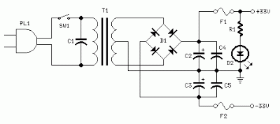
Parts:
R1____________3K3 1/2W Resistor C1___________10nF 1000V Polyester CapacitorC2,C3______4700µF 50V Electrolytic CapacitorsC4,C5_______100nF 63V Polyester Capacitors D1__________200V 8A Diode bridgeD2__________5mm. Red LED F1,F2_______3.15A Fuses with sockets T1__________220V Primary, 25 + 25V Secondary 120VA Mains transformer PL1_________Male Mains plug SW1_________SPST Mains switchNotes:
- Can be directly connected to CD players, tuners and tape recorders. Simply add a 10K Log potentiometer (dual gang for stereo) and a switch to cope with the various sources you need.
- Q6 & Q7 must have a small U-shaped heatsink.
- Q8 & Q9 must be mounted on heatsink.
- Adjust R11 to set quiescent current at 100mA (best measured with an Avo-meter connected in series to Q8 Drain) with no input signal.
- A correct grounding is very important to eliminate hum and ground loops. Connect to the same point the ground sides of R1, R4, R9, C3 to C8. Connect C11 to output ground. Then connect separately the input and output grounds to power supply ground.
- An earlier prototype of this amplifier was recently inspected and tested again after 15 years of use.
Technical data:
Output power:
well in excess of 25 Watt RMS @ 8 Ohm (1KHz sine wave)
Sensitivity:
200mV input for 25W output
Frequency response:
30Hz to 20KHz-1dB
Total harmonic distortion @ 1KHz:
0.1W 0.014% 1W 0.006% 10W 0.006% 20W0.007% 25W 0.01%
Total harmonic distortion @10KHz:
0.1W 0.024% 1W 0.016% 10W 0.02% 20W0.045% 25W 0.07%
Unconditionally stable on capacitive loads
Friday, October 24, 2014
25 Watt Audio Amplifier Circuits Diagram
25 Watt Audio Amplifier Circuits Diagram
Parts:
R1,R4_________47K 1/4W Resistors
R2____________4K7 1/4W ResistorR3____________1K5 1/4W ResistorR5__________390R 1/4W ResistorR6__________470R 1/4W ResistorR7___________33K 1/4W ResistorR8__________150K 1/4W ResistorR9___________15K 1/4W ResistorR10__________27R 1/4W ResistorR11_________500R 1/2W Trimmer Cermet
R12,R13,R16__10R 1/4W Resistors
R14,R15_____220R 1/4W Resistors
R17___________8R2 2W ResistorR18____________R22 4W Resistor (wirewound)
C1___________470nF 63V Polyester CapacitorC2___________330pF 63V Polystyrene CapacitorC3,C5________470µF 63V Electrolytic Capacitors
C4,C6,C8,C11_100nF 63V Polyester Capacitors
C7___________100µF 25V Electrolytic CapacitorC9____________10pF 63V Polystyrene CapacitorC10____________1µF 63V Polyester CapacitorQ1-Q5______BC560C 45V 100mA Low noise High gain PNP TransistorsQ6_________BD140 80V 1.5A PNP TransistorQ7_________BD139 80V 1.5A NPN TransistorQ8_________IRF530 100V 14A N-Channel Hexfet Transistor
Q9_________IRF9530 100V 12A P-Channel Hexfet TransistorPower supply circuit diagram
Parts:
R1____________3K3 1/2W Resistor C1___________10nF 1000V Polyester CapacitorC2,C3______4700µF 50V Electrolytic CapacitorsC4,C5_______100nF 63V Polyester Capacitors D1__________200V 8A Diode bridgeD2__________5mm. Red LED F1,F2_______3.15A Fuses with sockets T1__________220V Primary, 25 + 25V Secondary 120VA Mains transformer PL1_________Male Mains plug SW1_________SPST Mains switchNotes:
- Can be directly connected to CD players, tuners and tape recorders. Simply add a 10K Log potentiometer (dual gang for stereo) and a switch to cope with the various sources you need.
- Q6 & Q7 must have a small U-shaped heatsink.
- Q8 & Q9 must be mounted on heatsink.
- Adjust R11 to set quiescent current at 100mA (best measured with an Avo-meter connected in series to Q8 Drain) with no input signal.
- A correct grounding is very important to eliminate hum and ground loops. Connect to the same point the ground sides of R1, R4, R9, C3 to C8. Connect C11 to output ground. Then connect separately the input and output grounds to power supply ground.
- An earlier prototype of this amplifier was recently inspected and tested again after 15 years of use.
Technical data:
Output power:
well in excess of 25 Watt RMS @ 8 Ohm (1KHz sine wave)
Sensitivity:
200mV input for 25W output
Frequency response:
30Hz to 20KHz-1dB
Total harmonic distortion @ 1KHz:
0.1W 0.014% 1W 0.006% 10W 0.006% 20W0.007% 25W 0.01%
Total harmonic distortion @10KHz:
0.1W 0.024% 1W 0.016% 10W 0.02% 20W0.045% 25W 0.07%
Unconditionally stable on capacitive loads
Boster 15 watt rd 15 no tune
15 rd booster requires only 0.5 watts of input capable of out 15 watts, the voltage of 13.8 volts it needs. in this series are made to work freq 87-108 mhz fm broadcast. but did not rule to be modified in other freq. schematic and pcb layout to please download here
.JPG)
Thursday, October 23, 2014
200 Watt Amplifier Circuit Diagram using TDA2030
This is a 200 Watt Amplifier Circuit Diagram that uses a TDA2030 IC which is an audio power amplifier 200 watt low cost. The 200 watts can be achieved with a load impedance of 4 ohms. The TDA2030 can typically provide up to 14 watts into a 4 ohm load, but if used in bridge mode and we use some cheap power transistors we can get to 200 watt. The design of this amplifier circuit 200 watt audio is very simple and requires few external components. For best performance, you can use a source of 28 volts (+ / - 14 volts), not more than 44 volts (+ / - 20 volts).
As you can see in the diagram, for this power amplifier circuit you need high capacity capacitors and a power supply high current. All transistors and ICS should be mounted on a heat sink to prevent damage by temperature. For small value resistors (1 ohm, 2.2 ohm) resistors use 2-5 watts.
200 Watt Amplifier Circuit Diagram using TDA2030

Monday, October 20, 2014
Simple 8 Watt Audio Power Amplifier Schematic
Here is the schematic for an 8 watt audio power amplifier. This amp can be used as a simple booster, the heart of a more complicated amplifier or used as a guitar amp. It is very small and portable unit and can be powered through 12V battery. I built the circuit on a Vero Board and had to add extra inductors, capacitors and resistors to prevent oscillation.
Circuit diagram:

8 Watt Audio Power Amplifier Circuit Diagram
Parts:
R1 = 47K
R2 = 2.2R/1W
R3 = 220R/1W
R4 = 2.2R/1W
C1 = 100nF-63V
C2 = 10uF-25V
C3 = 470uF-25V
C4 = 2000uF-25V
C5 = 100nF-63V
IC1 = LM383
SPKR = 4ohm/8W
Notes:
- IC1 must be installed on a heat sink.
- C1 is for filtering and to prevent oscillation and should not be omitted.
- The circuit can be built on a Vero Board, universal solder board or PC board, the PC board is preferred.
- The circuit draws about 880Ma at 12 V.
- By swapping the values of R2 and R3; you can turn this amplifier into a guitar amp with no preamp required.
- If you cant find 2000uF, then replace C4 with a 2200uF unit.
- If you add a 0.2uF capacitor in series with a 1 ohm resistor to the output you can prevent oscillation of the circuit under certain conditions.
Tuesday, October 14, 2014
LM4765 create 2 x 30 watt amplifier
A very simple 2 x 30 watt amplifier electronic circuit project can be designed using the LM4765 stereo audio amplifier IC capable of delivering typically 30W per channel of continuous average output power into an 8Ω load with less than 0.1% THD+N.
This 2 x 30 watt amplifier electronic circuit is very simple and require few external electronic parts and can be used in high end stereo TVs or some other audio applications .
Each amplifier has an independent smooth transition fadein/out mute and a power conserving standby mode which can be controlled by external logic.
Like many other audio amplifier ICs the LM4765 has many features like Temperature protection circuitry, SPiKe protection ( means that these parts are safeguarded at the output against overvoltage, undervoltage, overloads, including thermal runaway and instantaneous temperature peaks).
This audio amplifier electronic circuit project can be powered from a wide input voltage range from 20 volt up to 66 volts , but typically is required a dual 28 volts input ( take care because |Vcc|+|Vee|<60 volts .
The LM4765 has a sophisticated thermal protection scheme to prevent long-term thermal stress of the device. When the temperature on the die reaches 165°C, the LM4765 shuts down. It starts operating again when the die temperature drops to about 155°C, but if the temperature again begins to rise, shutdown will occur again at 165°C.
The audio IC must be mounted on a heat sink to keep the die temperature at a level such that the thermal protection circuitry does not operate under normal circumstances.
In this circuit diagram is represented just a part of the IC (one channel ) and numbers in parentheses represent pinout for amplifier B.
This 2 x 30 watt amplifier electronic circuit is very simple and require few external electronic parts and can be used in high end stereo TVs or some other audio applications .
Each amplifier has an independent smooth transition fadein/out mute and a power conserving standby mode which can be controlled by external logic.
Like many other audio amplifier ICs the LM4765 has many features like Temperature protection circuitry, SPiKe protection ( means that these parts are safeguarded at the output against overvoltage, undervoltage, overloads, including thermal runaway and instantaneous temperature peaks).
This audio amplifier electronic circuit project can be powered from a wide input voltage range from 20 volt up to 66 volts , but typically is required a dual 28 volts input ( take care because |Vcc|+|Vee|<60 volts .
The LM4765 has a sophisticated thermal protection scheme to prevent long-term thermal stress of the device. When the temperature on the die reaches 165°C, the LM4765 shuts down. It starts operating again when the die temperature drops to about 155°C, but if the temperature again begins to rise, shutdown will occur again at 165°C.
The audio IC must be mounted on a heat sink to keep the die temperature at a level such that the thermal protection circuitry does not operate under normal circumstances.
In this circuit diagram is represented just a part of the IC (one channel ) and numbers in parentheses represent pinout for amplifier B.
Friday, October 3, 2014
60 Watt Guitar Amplifier with Tone Control
The following is a circuit of amplifiers are equipped with the suitable regulatory tone in use to strengthen the electric guitar, employing a single-rail supply of regarding 60V and capacitor-coupling for the speaker . the benefits for a guitar amplifier are the terribly simple circuitry, even for comparatively high power outputs, and an explicit built-in degree of loudspeaker protection, owing to capacitor C8, preventing the voltage supply to be conveyed into loudspeakers in case of output transistors failure.
In all cases where Darlington transistors are used because the output devices it is essential that the sensing transistor (Q2) should be in as close thermal contact with the output transistors as potential. thus a TO126-case transistor sort was chosen for straightforward bolting on the heatsink, terribly near the output combine
R30 must be cut so as to live regarding half the voltage supply across the positive lead of C7 and ground. an improved setting is done using an oscilloscope, so as to get a symmetrical clipping of the output wave type at most output power
Note:
To set quiescent current, tide ampare meter in series between supplay with this series, then do the following
- Set the volume control to the minimum and Trimmer R3 to its minimum resistance.
- Power-on the circuit and adjust R3 to read a current drawing of about 30 to 35mA.
- Wait about 15 minutes, watch if the current is varying and readjust if necessary.
List component
R1,R2______________68K 1/4W Resistors
R3________________680K 1/4W Resistor
R4________________220K 1/4W Resistor
R5_________________33K 1/4W Resistor
R6,R16______________2K2 1/4W Resistors
R7__________________5K6 1/4W Resistor
R8,R21____________330R 1/4W Resistors
R9_________________47K 1/4W Resistor
R10_______________470R 1/4W Resistor
R11_________________4K7 1/4W Resistor
R12,R20____________10K 1/4W Resistors
R13_______________100R 1/4W Resistor
R14,R15____________47R 1/4W Resistors
R17,R18,R19_______100K 1/4W Resistors
R22__________________6K8 1W Resistor
R23,R25_____________470R 1/4W Resistors
R24__________________2K 1/2W Trimmer Cermet
R26,R27_______________4K7 1/2W Resistors
R28________________220R 1/2W Resistor
R29__________________2K2 1/2W Resistor
R30_________________50K 1/2W Trimmer Cermet
R31________________68K 1/4W Resistor
R32,R33______________R47 4W Wirewound Resistors
C1,C4,C5,C6________10µF 63V Electrolytic Capacitors
C2_________________47µF 63V Electrolytic Capacitor
C3_________________47pF 63V Ceramic Capacitor
C7_________________15nF 63V Polyester Capacitor
C8_________________22nF 63V Polyester Capacitor
C9________________470nF 63V Polyester Capacitor
C10,C11,C12________10µF 63V Electrolytic Capacitors
C13_______________220µF 63V Electrolytic Capacitor
C14,C15,C17,C18________47µF 63V Electrolytic Capacitors
C16________________100µF 25V Electrolytic Capacitor
C19_________________33pF 63V Ceramic Capacitor
C20_______________1000µF 50V Electrolytic Capacitor
P1,P2______________10K Potentiometers
P3_________________10K Potentiometer

D1,D2____________BAT46 100V 150mA Schottky-barrier Diodes
D3_________________LED

Q1,Q3____________BC546 NPN Transistors
Q2_______________BC556 PNP Transistor
Q4,Q5____________BD139 80V 1.5A NPN Transistors
Q6_____________MJ11016 120V 30A NPN Darlington Transistor
Q7_____________MJ11015 120V 30A PNP Darlington Transistor

J1,J2___________6.3mm. Mono Jack sockets
SW1,SW2___________SPST Switches
SPKR______________speakers 8 or 4 Ohm with Minimum power 75W
Saturday, September 20, 2014
5 Watt Class A Audio Amplifier Circuit diagram
This solid-state push-pull single-ended Class A schema is capable of providing a sound comparable to those valve amplifiers, delivering more output power (6.9W measured across a 8 Ohm loudspeaker cabinet load), less THD, higher input sensitivity and better linearity. Voltage and current required for this schema are 24V and 700mA respectively, compared to 250V HT rail and 1A @ 6.3V filament heating for valve-operated amplifiers. The only penalty for the transistor operated schema is the necessity of using a rather large Heatsink for Q2 and Q3 (compared to the maximum power delivered).In any case, the amount of heat generated by this schema can be comparable to that of a one-valve amplifier. An optional bass-boost facility can be added, by means of R5 and C5.
5 Watt Class-A Audio Amplifier Circuit diagram
Parts:
P1 = 47K
R1 = 100K
R2 = 12K
R3 = 47K
R4 = 8.2K
R5 = 1.5K
R6 = 2.7K
R7 = 100R
R8 = 100R
R9 = 560R-1/2W
R10 = 1R-1/2W
Q1 = BC560
Q2 = BD439
Q3 = BD439
C1 = 10uF-63V
C2 = 10uF-63V
C3 = 47uF-25V
C4 = 100uF-35V
C5 = 150nF-63V
C6 = 220uF-25V
C7 = 220uF-25V
C8 = 1000uF-25V
SPKR = 5W-8R Speaker
Notes:
- If necessary, R2 can be adjusted to obtain 13V across C8 positive lead and negative ground.
- Total current drawing of the schema, best measured by inserting the probes of an Avo-meter across the positive output of the power supply and the positive rail input of the amplifier, must be 700mA. Adjust R8 to obtain this value if necessary.
- Q2 and Q3 must be mounted on a finned Heatsink of 120x50x25mm. Minimum dimensions.
- Add R5 and C5 if the bass-boost facility is required.
Thursday, September 11, 2014
Build a Simple 10 Watt Power Amplifier Wiring diagram Schematic
The aim of the project was to make an audio amplifier that can deliver up to 10W R.M.S. power output.
Risk of instability if no input connected. When testing, connect R (about 3k3).
Needs well smoothed power supply of about 20 to 30 volts. Peak power is well over 10 Watts.
The table below shows the approximate voltages to be expected when using a 24v supply and with the variable resistor set to give a current of about 40mA in the output stage.
| ||||||||||||||||||
Transistors:
Tr1 BCY70 (or BC 182L or BC212L or BC214L)
Tr2/3/4 BFY50/51
Tr5 BFX88
Tr6/7 2N3055
Tr1 BCY70 (or BC 182L or BC212L or BC214L)
Tr2/3/4 BFY50/51
Tr5 BFX88
Tr6/7 2N3055
Simple 10 Watt Power Amplifier Circuit Diagram
Component Side
Copper Side
Wednesday, September 3, 2014
1 6 Watt intregated circuit audio amplifier
This Circut based on IC TDA7231 , Minimum voltage require 2 Volts and maximum voltage 15 volts . I recomended voltage is 12 volt DC. Power output 1,6 Watt with 4 Ohm impedance. See audio amplifier with IC TDA7231 below :

Saturday, August 30, 2014
50 Watt Subwoofer Amplifier

R1 200 Ohm 1/4 W Resistor
R2 200K 1/4 W Resistor
R3 30K 1/4 W Resistor
R5 1K 1/4 W Resistor
R6 5K 1/4 W Resistor
R7,R10 Meg (5%) 1/2 W Resistor
R8,R9 0.4 Ohm 5 W Resistor
R11 10K Pot
R12,R13 51K 1/4 W Resistor
R14 47K 1/4 W Resistor
C1 100uF 35V Electrolytic Capacitor
C2 0.011uF Capacitor
C3 3750pF Capacitor
C4,C6 1000pF Capacitor
C5,C7,C8 0.001uF Capacitor
C9 50pF Capacitor
C10 0.3uF Capacitor
C11,C12 10,000uF 50V Electrolytic Capacitor
U1,U2 741 Op Amp
U3 ICL8063 Audio Amp Transister Driver thingy
Q1 2N3055 NPN Power Transistor
Q2 2N3791 PNP Power Transistor
BR1 250 V 6 Amp Bridge Rectifier
T1 50V Center Tapped 5 Amp Transformer
S1 SPST 3 Amp Switch
S2 DPDT Switch
F1 2 Amp Fuse
SPKR1 8 Ohm 50W Speaker
MISC Case, Knobs, Line Cord, Binding Posts Or Phono Plugs (For Input And Output), Heatsinks For Q1 And Q2
Friday, August 29, 2014
2 X 30 Watt stereo amplifier by TDA1510
This power amplifier can use IC TDA1510 or TDA1515, minimum voltage require 6 volt and maximum voltage require 18 Volt, Voltage with DC supply voltage.Power output 2x 30 Watt stereo amplifier , with 2 ohms impedance , its is low impedance . You can use the fullrange or woofer speakers. see schematic below :

Subscribe to:
Posts (Atom)
