Showing posts with label to. Show all posts
Showing posts with label to. Show all posts
Saturday, October 25, 2014
3000 watt power inverter 12V DC to 230V AC
3000 watt power inverter 12V DC to 230V AC
 |
| Circuit Diagram of 3000 watt power inverter 12V DC to 230V AC |
 |
| Fig. 2: Sine-wave voltage and conventional square wave voltage with both 230 Volt rms |
 |
| Fig. 3: Square wave voltage with duty cycle 25% for 230 Volt rms ("modified sine") |
PCB Layout:3000 watt power inverter 12V DC to 230V AC

Component Placement: 3000 watt power inverter 12V DC to 230V AC

 |
| fig.: output voltage with no load or inductive load. |
 |
| fig.: resistor 0,001 Ohm made of high-grade steel sheet metal |
Control electronics | 3000 watt power inverter 12V DC to 230V AC

 |
| fig.: control electronics on strip hole plate (previous version) and PCB of the "professional edition" |
Assembly of the mosfet-transistors on the heat sink | 3000 watt power inverter 12V DC to 230V AC

 |
| fig.: heat sink, mosfet transistors, connections. |
Final assembly | 3000 watt power inverter 12V DC to 230V AC

 |
| fig.: 1500 VA inverter with 2 parallel transformers and 1000 VA inverter |
Source:http://www.qsl.net

Friday, October 24, 2014
Converter RS232 to Arduino Circuit Diagram

The circuit in this article is an RS232 converter, it is possible to connect an Arduino bootloader or your chip with a RS232 port. Here are two versions, one very simple and functional above and one below a little more sophisticated. The port 232 gives a bit more work than USB, but in case of equipment that only have this feature that is a good outlet.
Converter RS232 to Arduino Circuit Diagram

Thursday, October 23, 2014
How to Make your own Breadboard
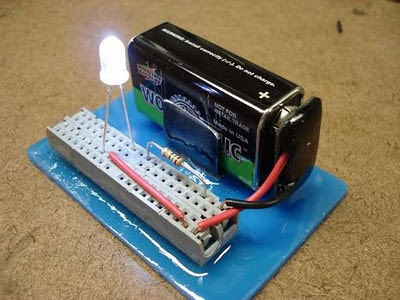
Often we do not have the opportunity or the money to keep our hobby, sometimes we lack tools, but always there is a knack for everything, is what we see here in this article was originally published at indestructible. He teaches you how to make your own breadboard using scrap old computers, in fact it uses sockets IDE cable. The breadboard makes life easier for those who like to create electronic circuits, and can only plug components without using solder.

1 3V DC to 12 2V DC Regulator Power Supply
Power supply circuit to generate output below were variations between 1.3V DC to 12.2V DC with 1A current.
In addition, the power supply circuit is also equipped with over-current protection or shield against belebih flow. Power supply circuit is very simple, but the quality is quite good, made her basiskan regulator IC LM723 is a pretty legendary.
In addition, the power supply circuit is also equipped with over-current protection or shield against belebih flow. Power supply circuit is very simple, but the quality is quite good, made her basiskan regulator IC LM723 is a pretty legendary.

Description:
R2 to set the output voltage. The maximum current is determined by R3, over-current protection circuit inside the LM723 to detect the voltage on R3, if it reaches 0.65 V, the voltage output will be off her. So the current through R3 can not exceed 0.65 / R3 although output short-circuit in his.
C3 and C4 are ceramic capacitors, as much as possible directly soldered to the PCB, this is because the LM723 is prone to oscillation that is not cool.
LM723 works with 9.5V input voltage to 40 V DC and the LM723 can generate its own current of 150mA when the output voltage is not more than 6-7V under input voltage.
Specifications:
Output (value estimated):
Vmin = (R4 + R5) / (R5 * 1.3)
Vmax = (7.15 / R5) * (R4 + R5)
Imax = 0.65/R3
Max. Power on R3: 0.42/R3
Min. DC Input Voltage (pin 12 to pin 7): Vmax + 5
Component List:
B1 40V/2.5A
C1 2200uF (3300uF even better)
C2 4.7uF
C3 100nF
C4 1NF
C5 330nF
C6 100uF
Green LED D1
D2 1N4003
F1 0.2A F
F2 2A M
IC1 LM723 (in a DIL14 plastic package)
R1 1k
R2 Pot. 5k
R3 0.56R/2W
R4 3.3k
R5 4.7k
S1 250V/1A
T1 2N3055 on a heatsink 5K / W
TR1 220V/17V/1.5
Saturday, October 18, 2014
5V to 12V DC LM2577 Converter step up Voltage Regulator
This is Circuit DC to DC Converter Step up Voltage Regulator From 5V To 12V 1A Regulated Output.

LM2577 (3A)
DC to DC step up voltage regulator.
Wide input voltage 3.5Vdc to 40Vdc.
Component list
- 2.2k 1/4W resistor
- 0.1uF capacitor
- 0.33uF capacitor
- 680uF 50V electrolytic capacitor
- 1N5822 high speed schottky diode (3A)
- wire coil inductor, 100uH
- “for LM2577-adj IC” 20k multi-turn variable resistor, set to ratio to R2=2k, R1=18k for voltage output of 12Vdc before soldering
Part number:
- LM2577-12 (12Vdc output)
- LM2577-15 (15Vdc output)
- LM2577-ADJ (1.23Vdc to 37Vdc output)
LM2577 (3A)
DC to DC step up voltage regulator.
Wide input voltage 3.5Vdc to 40Vdc.
Component list
- 2.2k 1/4W resistor
- 0.1uF capacitor
- 0.33uF capacitor
- 680uF 50V electrolytic capacitor
- 1N5822 high speed schottky diode (3A)
- wire coil inductor, 100uH
- “for LM2577-adj IC” 20k multi-turn variable resistor, set to ratio to R2=2k, R1=18k for voltage output of 12Vdc before soldering
Part number:
- LM2577-12 (12Vdc output)
- LM2577-15 (15Vdc output)
- LM2577-ADJ (1.23Vdc to 37Vdc output)
Friday, October 17, 2014
5 to 15V Regulated Power Supply
Regulated Power Supply

Fuse F1 is used as a protection in case theres any short circuit in the circuit. Varistor V1 is connected in parallel to the input of the line voltage to clamp the surge voltage from the line to a reasonable level that helps to protect the transformer & other circuitry. One time the voltage level surge to a high level beyond the ability of the varistor to absorb it, fuse F1 or varistor V1 or both will burn. If this circuit failed after a period of operation, check that the fuse & the varistor are still in nice condition or else replace them.

This project is a normal DC regulated power supply that is a variable DC voltage range from 5V to 15V. It can supply current up to 400mA to power the various circuits for your electronic projects. The voltage output is varied by using the potentiometer V.R1. In this circuit, the input line power supply is designed for 240V.A.C. If 110VAC input is used, alter the ratings of the varistor to 150VAC & the transformer ratio to 110V/12V.
Fuse F1 is used as a protection in case theres any short circuit in the circuit. Varistor V1 is connected in parallel to the input of the line voltage to clamp the surge voltage from the line to a reasonable level that helps to protect the transformer & other circuitry. One time the voltage level surge to a high level beyond the ability of the varistor to absorb it, fuse F1 or varistor V1 or both will burn. If this circuit failed after a period of operation, check that the fuse & the varistor are still in nice condition or else replace them.
Diodes D1, D2, D3 and D4 are used to rectify the 12V.A.C voltage to DC voltage. Electrolytic capacitor E1 is used as a smoothing capacitor to reduce the ripple of the DC voltage. The DC voltage is fed in to the input of 7805 regulator where the output DC voltage is obtained. Changing the worth of VR1 will alter the output of the DC voltage. Capacitor C1 is used to filter out high frequency part from the power supply.
Thursday, October 16, 2014
Variable 5 to 20V DC Supply Rise
This is a Variable 5 to 20V DC Supply Circuit Diagram. If you are looking for a low drop voltage regulator that can provide a power supply of 1A with an output voltage of between 5V and 20V DC, National Semiconductor LM2941 Low Dropout Adjustable Regulator is that you can pick to make use of. Its a typical dropout voltage of 0.5V which means that the input supply need only must be 0.5V DC over the desired output voltage.
Variable 5 to 20V DC Supply Circuit Diagram

Its other features include internal short circuit current limit and reverse battery protection. As shown in the schematic below, the regulator has five pins which consists of the ON/OFF control, Input Voltage, Output Voltage, Ground & Adjustable pins. ON/OFF is used for the purpose of switching on & off of the regulator. The capacitors C1 & E1 are to be placed as close as feasible to the regulator.
The output of the circuit can be varied by varying the worth of potentiometer VR1 from 5V DC to 20V DC. The input voltage is limited from five.5V DC to 30V DC. Resistor R1 must be greater than 1K. The worth of the VR1 that needs to be set is calculated from the formula given below:
VR1 = R1[(Vout/1.275) - 1] ohm
If R1=1K, Vout = 5V, VR1 should be set to 2.9K ohm.
If R1=1K, Vout = 20V, VR1 should be set to 14.7K ohm

Simple 500W Inverter 12 Volt to 220 Volt Circuit Diagram
This is the Simple 500W Inverter 12 Volt to 220 Volt Circuit Diagram about the the inverter, because like working outdoors, or to backup storage to use when necessary. Most of this is circuit low power, which is not suitable for practical applications. My friends said that he would be about 500 Watt. It is a good size. Use with television receivers and light bulbs as well. When looking for circuit. I get headaches.
500W Inverter 12 Volt to 220 Volt Circuit Diagram

If you are a beginner or I can not buy expensive good quality circuits. Requires only one transistor. Or if you have free time. I want to build old circuit is alive again. This circuit will accommodate all your needs. It is a simple circuit. The same principle, I take battery voltage 12V to produce a oscillator about 100 Hz and pass to a two frequency divider circuit is only 50HZ. and drive a 10 ampere transformer with 10 x 2N3055 transistor in parallel.
By a single transistor has 2A, when I use 10 transistors or 5 pairs of drive high current output. The complexity of circuit, but the principle is not it, and it is the number of transistors on a basic, easy to buy. You may be modified 100 watt power inverter To the size of transistors and transformers as well.
Note:
If you think that This circuit is not good enough. For your work. It is hard to find equipment. You do not have it now. These circuits may be viewed below. It may be appropriate for you.Source: leksound project
Saturday, September 20, 2014
Build a 500W low cost 12V to 220V Inverter Circuit Diagram
Build a 500W low cost 12V to 220V Inverter Circuit Diagram. Using this circuit you can convert the 12V dc in to the 220V Ac. In this circuit 4047 is use to generate the square wave of 50hz and amplify the current and then amplify the voltage by using the step transformer.
500W low cost 12V to 220V Inverter Circuit Diagram
How to calculate transformer rating
The basic formula is P=VI and between input output of the transformer we have Power input = Power output
For example if we want a 220W output at 220V then we need 1A at the output. Then at the input we must have at least 18.3V at 12V because: 12V*18.3 = 220v*1
So you have to wind the step up transformer 12v to 220v but input winding must be capable to bear 20A.
Attention: This Circuit is using high voltage that is lethal. Please take appropriate precautions
Author:Ashad Mustufa, mustufa66@hotmail.com
Tuesday, September 16, 2014
12 VDC to 120 VAC Inverter Circuit
12 VDC to 120 VAC Inverter Circuit
Ever bare a low ability 120volt AC ability antecedent for your car, van or truck? Well this ambit should do the ambush for you. It will accumulation 15 watts of AC ability to a device. It should ability lamps, shavers, baby stereos and baby appliances. If you draw to abundant ability the ambit will shut bottomward all by itself. The achievement of this ambit is a aboveboard beachcomber so there may be some apparent hum on audio units acquainted into it. To abate some of the hum access the amount of the achievement capacitor which is at .47uf now. That transistor in the ambit are aerial ability PNP transistors. Radio Shack allotment cardinal 276-2025 are acceptable ones to use or TIP32. The agent is a 24 volt 2 amp centermost broke accessory Radio Shack allotment cardinal 273-1512 or equivalent.
Saturday, September 13, 2014
Simple LT3582 12 DC 5V to 12V DC Converter
Using LT3582-12 dual channel DC DC converter integrated schema, manufactured by Linear Technology, can be designed a very simple step up dc converter. This 5 to 12V c converter electronic project provide both positive and negative outputs required in many biasing applications such as active matrix OLED (organic light-emitting diode)displays as well as CCD (charge coupled device) applications.
Simple LT3582-12 DC 5V to 12V DC Converter Circuit Diagram

Thursday, September 11, 2014
How to create a simple adjusting volume for amplifier
This circuit usually used for amplifier that do not require additional device in one box amplifiers. Enhancements such as Equalizer , Tone Control , Mixer , etc. Only by requiring a potentiometer mono or stereo if stereo power amplifier , and few cables you can make this circuit easily.
See picture below :

First connect the cable from the power amplifier input to pin2 potentio , and connect ground to pin 1 , then connect the output of tuner or other media player to pin 3. Try turning to the right then the sound will be high , and if played left back then the sound will below.
Monday, September 8, 2014
How to fix a plug


# If you are an underage be careful when you work with AC.So always get the assistance from an elder
Sunday, September 7, 2014
USB to phone battery charger circuit
Without any USB to phone battery charger circuit we can charging phone battery using port on USB computer , but it will quickly damage the phone battery, and the battery will bulge. Because the voltage which was issued on usb is 5 volts , while the average-voltage phone battery 3.5 - 3.7 volts. Thats why this USB to phone battery charger circuit is required , this USB to phone battery charger circuit reduce votlage to 3.7 volt usb, but will not reduce currents and will make a durable phone battery.
 |
| USB to phone battery charger circuit diagrams |
List of components :R1 : 1 KR2 : 330 RR3 : 4K7R4 : 300 RR5 : 27RD1 : 4.7 volt zener /1WC1 : 100uF/16VQ1 : BC548Q2 : BC558ALED1 : Green LedX1-1 : Vcc USBX1-4 : Ground USBX2-1 , X2-2 : To phone battery
See also this printed circuit board ( PCB ) of USB to phone battery charger :
 |
| USB to phone battery charger printed circuit board |
Friday, September 5, 2014
How to Dial in Your Cars Audio System
Level setting, done by ear, is more art than science. It can be done using an oscilloscope but since few people have one of those laying around well cover doing it by ear. Basically you want to start with the first component in the chain (the head unit) and work your way to the last component (the amplifier).
1. Start by turning all of the input level adjustment knobs (gain controls) on your components fully counter-clockwise (to their minimum setting). Set the tone controls (bass, treble, loudness) on your head unit to no boost (bass and treble level = 0 and loudness is off). If you have more than one RCA pair you will want to set each gain adjustment separately. Make sure your fader and balance controls are set to the channel you want to adjust first. This can be an individual channel if you have individual gain adjustments or a pair of channels if you have one gain for two channels.
2. Next set all of your equalizers settings (if you have an equalizer) to the center (detent) position so they produce no boost or cut. What we want is as pure a signal as possible.
3. Put in some good quality source material, preferably a CD with strong output and a clean recording. Hard rock would be a bad choice here. Try something cleaner, maybe acoustic, that youre familiar with.
4. Turn the decks volume up slowly until you begin to hear distortion. When you hear it, stop and back off slightly until you no longer hear it. If you dont hear distortion, even when the volume is all of the way up then you have a quality head unit. Thats what were looking for.
5. Now with your head unit at maximum undistorted volume move on to the next component. Adjust its input gain until you begin to hear distortion. Back off slightly.
6. Continue this process until you have all of the components in the chain at their maximum undistorted level.
7. When you reach the amplifiers you may need to wear earplugs to adjust them to their maximum level. As before, turn up the gain until you hear audible distortion. This should be audible even with earplugs in. But honestly, if you have to wear earplugs to listen the distortion level is probably not a factor :)
Thats it. Play some music and verify that everything sounds right. Congratulations! Youve just learned to properly adjust the settings on your car audio system.
Read More..
1. Start by turning all of the input level adjustment knobs (gain controls) on your components fully counter-clockwise (to their minimum setting). Set the tone controls (bass, treble, loudness) on your head unit to no boost (bass and treble level = 0 and loudness is off). If you have more than one RCA pair you will want to set each gain adjustment separately. Make sure your fader and balance controls are set to the channel you want to adjust first. This can be an individual channel if you have individual gain adjustments or a pair of channels if you have one gain for two channels.
2. Next set all of your equalizers settings (if you have an equalizer) to the center (detent) position so they produce no boost or cut. What we want is as pure a signal as possible.
3. Put in some good quality source material, preferably a CD with strong output and a clean recording. Hard rock would be a bad choice here. Try something cleaner, maybe acoustic, that youre familiar with.
4. Turn the decks volume up slowly until you begin to hear distortion. When you hear it, stop and back off slightly until you no longer hear it. If you dont hear distortion, even when the volume is all of the way up then you have a quality head unit. Thats what were looking for.
5. Now with your head unit at maximum undistorted volume move on to the next component. Adjust its input gain until you begin to hear distortion. Back off slightly.
6. Continue this process until you have all of the components in the chain at their maximum undistorted level.
7. When you reach the amplifiers you may need to wear earplugs to adjust them to their maximum level. As before, turn up the gain until you hear audible distortion. This should be audible even with earplugs in. But honestly, if you have to wear earplugs to listen the distortion level is probably not a factor :)
Thats it. Play some music and verify that everything sounds right. Congratulations! Youve just learned to properly adjust the settings on your car audio system.
Sunday, August 31, 2014
Build a Voltage To Frequency Converter Wiring diagram Schematic 2
Build a Voltage-To-Frequency Converter Circuit Diagram 2. Using a Burr-Brown VFC 32 IC, this voltage-to-frequency converter uses few components. The schema values are shown in the figure. This charge-balanced V/F converter uses a VFC32 or a VFC320 IC.
The positive charge from the 1-mA balances the negative charge from the input. V/F converter waveforms are shown in Fig. 100-l(b).
Voltage-To-Frequency Converter Circuit Diagram 2
Simple 12V to 250V Converter
A very simple portable 12v to 250V converter can be designed using this schema diagram. This 12 to 250V converter is designed for portable use with a 12 V car battery.A built astabil multivibrator T1 and T2 generates a rectangular wave at a frequency of 50 Hz. As T1 and T2 drive alternative exit stage system also works in "push-pull". When T1 lead by passing a current T3: T5 and that it engages the latter transistor connects to a half battery of 12 V secondary winding of the transformer Tr When T2 network drive, T6 transistor coupled to the battery the other half of the network adapter.
Simple 12V to 250V Converter Circuit Diagram
If it is used for output stages 40 411 RCA transistors, the current through secondary winding can be up to 10 A, giving a power output of 180 watts. If you use 2N3055 transistors, power output will be about 90 watts. Since the output transistors are driven to saturation, they have very high mounted radiators.Although schema is simple construction and has high efficiency disadvantage is rectangular output voltage which, in the absence of a regulator is dependent on task: small loads, the output voltage is 250 V ac (not working properly for the engine speed control, light dimmers, televisions, hi-fi equipment.
Thursday, August 28, 2014
How to Build 1 2 30V 1 5A Variable Regulated Power supply Circuit
How to Build 1.2-30V/1.5A Variable Regulated Power supply, This is simple 1.2-30V/1.5A variable regulated power supply schema diagram The 110V-AC coming from the powercord is fed to the transformer TR1 via the on-off switch and the 500mA fuse. The 30vac output (approximately) from the transformer is presented to the BR1, the bridge-rectifier, and here rectified from AC (Alternating Current) to DC (Direct Current). If you dont want to spend the money for a Bridge Rectifier, you can easily use four general purpose 1N4004 diodes. The pulsating DC output is filtered via the 2200µF capacitor (to make it more manageable for the regulator) and fed to IN-put of the adjustable LM317 regulator (IC1). The output of this regulator is your adjustable voltage of 1.2 to 30volts varied via the Adj pin and the 5K potmeter P1. The large value of C1 makes for a good, low ripple output voltage.
1.2-30V/1.5A Variable Regulated Power supply Circuit Diagram
Why exactly 1.2V and not 0-volt? Very basic, the job of the regulator is two-fold; first, it compares the output voltage to an internal reference and controls the output voltage so that it remains constant, and second, it provides a method for adjusting the output voltage to the level you want by using a potentriometer. Internally the regulator uses a zener diode to provide a fixed reference voltage of 1.2 volt across the external resistor R2. (This resistor is usually around 240 ohms, but 220 ohms will work fine without any problems). Because of this the voltage at the output can never decrease below 1.2 volts, but as the potentiometer (P1) increases in resistance the voltage accross it, due to current from the regulator plus current from R2, its voltage increases. This increases the output voltage.
D1 is a general purpose 1N4001 diode, used as a feedback blocker. It steers any current that might be coming from the device under power around the regulator to prevent the regulator from being damaged. Such reverse currents usually occur when devices are powered down.
The ON Led will be lit via the 18K resistor R1. The current through the led will be between 12 - 20mA @ 2V depending on the type and color Led you are using. C2 is a 0.1µF (100nF) decoupler capacitor to filter out the transient noise which can be induced into the supply by stray magnetic fields. Under normal conditions this capacitor is only required if the regulator is far away from the filter cap, but I added it anyway. C3 improves transient response. This means that while the regulator may perform perfectly at DC and at low frequencies, (regulating the voltage regardless of the load current), at higher frequencies it may be less effective. Adding this 1 µF capacitor should improve the response at those frequencies.
R3 and the trimmer pot (P2) alows you to zero your meter to a set voltage. The meter is a 30Volt type with an internal resistance of 85 ohms. I you have or obtained a meter with a different Ri (internal resistance) you will have to adjust R3 to keep the current of meter to 1mA. Just another note in regards this meter, use the reading as a guideline. The reading may or may not be off by about 0.75volts at full scale, meaning if your meter indicates 30 volts it may be in reality almost 31 volts or 29 volts. If you need a more precies voltage, then use your multimeter.
Construction:
Because of the few components you can use a small case but use whatever you have available. I used a power cord from a computer and cut the computer end off. All computer power cords are three-prong. The ground wire, which is connected to the middle pin of the power plug is connected to the chassis. The color of the ground-wire is either green or green/yellow. It is there for your protection if the 110vac accidentally comes in contact with the supply housing (case). BE CAREFUL always to disconnect the powerplug when you working inside the chassis. If you choose to use an in-line, or clip-type fuseholder be sure to isolate it with heat shrink or something to minimize accidental touching.
I use perf-board (or Vero board) as a schema board. This stuff is widely available and comes relatively cheap. It is either made of some sort of fiber material or Phenolic or Bakelite pcb. They all work great. Some Phenolic boards come with copper tracks already on them which will make soldering the project together easier.
I mounted the LM317(T) regulator on a heatsink. If you use a metal/aluminum case you can mount it right to the metal case, insulated with the mica insulator and the nylon washer around the mounting screw. Note that the metal tab of the LM317 is connected internally to the Output pin. So it has to be insulated when mounting directly to the case. Use heat sink compound (comes in transparent or white color) on the metal tab and mica insulator to maximize proper heat transfer between LM317 and case/ or heatsink.
Drill the holes for the banana jacks, on/off switch, and LED and make the cut-out for the meter. It is best to mount everything in such a way that you are able to trouble-shoot your schema board with ease if needed. One more note about the on-off switch S1, this switch has 110VAC power to it. After soldering, insulate the bare spots with a bit of silicon gel. Works great and prevents electrical shock through accidental touching.
If all is well, and you are finished assembling and soldering everything, check all connections. Check capacitors C1 & C3 for proper polarity (especially for C1, polarity reversal may cause explosion). Hookup a multimeter to the power supply output jacks. Set the meter for DC volts. Switch on S1 (led will light, no smoke or sparks?) and watch the meter movement. Adjust the potentiometer until it reads on your multimeter 15Volts. Adjust trimpot P2 until the meter also reads 15volts. When done, note any discrepancies between your multimeter and the power supply meter at full scale (max output). Maybe there is none, maybe there is a little, but you will be aware of it. Good luck and have fun building!

Parts List
BR1 = Bridge Rectifier, 100V - 3A C1 = 2200 µF, 63V
IC1 = LM317, adjustable regulator C2 = 0.1 µF
V = Meter, 30V, Ri = 85 ohm C3 = 1µF, 40V
TR1 = Transformer, 25V, 2A Plug = 3-wire plug & cord
R1 = 18K, 5% S1 = On-Off toggle switch
R2 = 220 ohm, 5% D1 = 1N4001
R3 = 27K, 5% Fuse = 110V, 500mA, slow-blow
P1 = 5K, potentiometer FuseHolder, wire, solder, case, knob for P1
P2 = 10K, 10-turn trim-pot Red & Black Banana Jacks
Notes:
This is a simple, but low-ripple powersupply, and an excellent project if youre starting out in electronics. It will suit your needs for most of your bench testing and prototype applications. The output is adjustable from 1.2 volts to about 30 volts. Maximum current is about 1.5 amps which is also sufficient for most of your tinkering. It is relatively easy to build and can be pretty cheap if you have some or all the required parts. A printed schema board is not included and Im not planning on adding one since the whole thing can easily be build on perferated or vero board. Or buy one of Radio Shack/Tandys experimentors boards (#276-150). Suit yourself. The meter and the transformer are the money suckers, but if you can scrounge them up from somewhere it will reduce the cost significantly. BR1 is a full-wave bridge rectifier. The two ~ denotes AC and are connected to the 25vac output coming from the transformer. IC1 is a 3-pin, TO-220 model. Be sure to put a cooling rib on IC1, at its max 1.5 A current it quickly becomes very hot..
All the parts can be obtained from your local Radio Shack or Tandy store. The physical size of the power supply case depends largely on the size of the meter & transformer. But almost anything will do. Go wild.
Sourced By Tony van roon
Subscribe to:
Posts (Atom)
