Showing posts with label 12v. Show all posts
Showing posts with label 12v. Show all posts
Saturday, October 25, 2014
3000 watt power inverter 12V DC to 230V AC
3000 watt power inverter 12V DC to 230V AC
 |
| Circuit Diagram of 3000 watt power inverter 12V DC to 230V AC |
 |
| Fig. 2: Sine-wave voltage and conventional square wave voltage with both 230 Volt rms |
 |
| Fig. 3: Square wave voltage with duty cycle 25% for 230 Volt rms ("modified sine") |
PCB Layout:3000 watt power inverter 12V DC to 230V AC

Component Placement: 3000 watt power inverter 12V DC to 230V AC

 |
| fig.: output voltage with no load or inductive load. |
 |
| fig.: resistor 0,001 Ohm made of high-grade steel sheet metal |
Control electronics | 3000 watt power inverter 12V DC to 230V AC

 |
| fig.: control electronics on strip hole plate (previous version) and PCB of the "professional edition" |
Assembly of the mosfet-transistors on the heat sink | 3000 watt power inverter 12V DC to 230V AC

 |
| fig.: heat sink, mosfet transistors, connections. |
Final assembly | 3000 watt power inverter 12V DC to 230V AC

 |
| fig.: 1500 VA inverter with 2 parallel transformers and 1000 VA inverter |
Source:http://www.qsl.net

Best Automatic 12V Lead Acid Battery Charger Circuit Diagram
Build a Best Automatic 12V Lead Acid Battery Charger Circuit Diagram. This Best Automatic 12V Lead Acid Battery Charger Circuit Diagram will charge any 12V lead acid battery including flooded, gel and AGM. It is fully automatic and will charge at a rate up to about 4A until the battery voltage reaches a preset point at which it will switch to a very low current float charge.
If the battery voltage drops again the charger will begin charging until the voltage once again reaches the cut off point. In this way it can be left connected to a battery indefinitely to maintain full charge without causing damage. An LED indicates when the battery is fully charged. Sourced By Circuitsstream
Best Automatic 12V Lead Acid Battery Charger Circuit Diagram
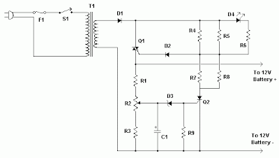
Commponents
Notes | R1, R3 | 2 | 330 Ohm 1/4W Resistor | |
| R2 | 1 | 100 Ohm 1/4W Pot | |
| R4, R5, R7, R8 | 4 | 82 Ohm 2W Resistor | |
| R6 | 1 | 100 Ohm 1/4W Resistor | |
| R9 | 1 | 1K 1/4W Resistor | |
| C1 | 1 | 220uF 25V Electrolytic Capacitor | |
| D1 | 1 | P600 Diode | Any 50V 5A or greater rectifier diode |
| D2 | 1 | 1N4004 Diode | 1N4002, 1N4007 |
| D3 | 1 | 5.6V Zener Diode | |
| D4 | 1 | LED (Red, Green or Yellow) | |
| Q1 | 1 | BT136 TRIAC | |
| Q2 | 1 | BRX49 SCR | |
| T1 | 1 | 12V 4A Transformer | See Notes |
| F1 | 1 | 3A Fuse | |
| S1 | 1 | SPST Switch, 120VAC 5A | |
| MISC | 1 | Wire, Board, Heatsink For U1, Case, Binding Posts or Alligator Clips For Output, Fuse Holder |
R2 will have to be adjusted to set the proper finish charge voltage. Flooded and gel batteries are generally charged to 13.8V. If you are cycling the battery (AGM or gel) then 14.5V to 14.9V is generally recommended by battery manufacturers. To set up the charger, set the pot to midway, turn on the charger and then connect a battery to its output. Monitor the charge with a voltmeter until the battery reaches the proper end voltage and then adjust the pot until the LED glows steadily. The charger has now been set. To charge multiple battery types you can mount the pot on the front of the case and have each position marked for the appropriate voltage.
Q1 will need a heatsink. If the circuit is mounted in a case then a small fan might be necessary and can generally be powered right off the output of D1.
T1 is a transformer with a primary voltage appropriate to your location (120V, 220V, etc.) and a secondary around 12V. Using a higher voltage secondary (16V-18V) will allow you to charge 16V batteries sometimes used in racing applications.
If the circuit is powered off, the battery should be disconnected from its output otherwise the circuit will drain the battery slowly.
Q1 will need a heatsink. If the circuit is mounted in a case then a small fan might be necessary and can generally be powered right off the output of D1.
T1 is a transformer with a primary voltage appropriate to your location (120V, 220V, etc.) and a secondary around 12V. Using a higher voltage secondary (16V-18V) will allow you to charge 16V batteries sometimes used in racing applications.
If the circuit is powered off, the battery should be disconnected from its output otherwise the circuit will drain the battery slowly.
Saturday, October 18, 2014
5V to 12V DC LM2577 Converter step up Voltage Regulator
This is Circuit DC to DC Converter Step up Voltage Regulator From 5V To 12V 1A Regulated Output.

LM2577 (3A)
DC to DC step up voltage regulator.
Wide input voltage 3.5Vdc to 40Vdc.
Component list
- 2.2k 1/4W resistor
- 0.1uF capacitor
- 0.33uF capacitor
- 680uF 50V electrolytic capacitor
- 1N5822 high speed schottky diode (3A)
- wire coil inductor, 100uH
- “for LM2577-adj IC” 20k multi-turn variable resistor, set to ratio to R2=2k, R1=18k for voltage output of 12Vdc before soldering
Part number:
- LM2577-12 (12Vdc output)
- LM2577-15 (15Vdc output)
- LM2577-ADJ (1.23Vdc to 37Vdc output)
LM2577 (3A)
DC to DC step up voltage regulator.
Wide input voltage 3.5Vdc to 40Vdc.
Component list
- 2.2k 1/4W resistor
- 0.1uF capacitor
- 0.33uF capacitor
- 680uF 50V electrolytic capacitor
- 1N5822 high speed schottky diode (3A)
- wire coil inductor, 100uH
- “for LM2577-adj IC” 20k multi-turn variable resistor, set to ratio to R2=2k, R1=18k for voltage output of 12Vdc before soldering
Part number:
- LM2577-12 (12Vdc output)
- LM2577-15 (15Vdc output)
- LM2577-ADJ (1.23Vdc to 37Vdc output)
Saturday, September 20, 2014
Build a 500W low cost 12V to 220V Inverter Circuit Diagram
Build a 500W low cost 12V to 220V Inverter Circuit Diagram. Using this circuit you can convert the 12V dc in to the 220V Ac. In this circuit 4047 is use to generate the square wave of 50hz and amplify the current and then amplify the voltage by using the step transformer.
500W low cost 12V to 220V Inverter Circuit Diagram
How to calculate transformer rating
The basic formula is P=VI and between input output of the transformer we have Power input = Power output
For example if we want a 220W output at 220V then we need 1A at the output. Then at the input we must have at least 18.3V at 12V because: 12V*18.3 = 220v*1
So you have to wind the step up transformer 12v to 220v but input winding must be capable to bear 20A.
Attention: This Circuit is using high voltage that is lethal. Please take appropriate precautions
Author:Ashad Mustufa, mustufa66@hotmail.com
Saturday, September 13, 2014
Simple LT3582 12 DC 5V to 12V DC Converter
Using LT3582-12 dual channel DC DC converter integrated schema, manufactured by Linear Technology, can be designed a very simple step up dc converter. This 5 to 12V c converter electronic project provide both positive and negative outputs required in many biasing applications such as active matrix OLED (organic light-emitting diode)displays as well as CCD (charge coupled device) applications.
Simple LT3582-12 DC 5V to 12V DC Converter Circuit Diagram

Sunday, August 31, 2014
Simple 12V to 250V Converter
A very simple portable 12v to 250V converter can be designed using this schema diagram. This 12 to 250V converter is designed for portable use with a 12 V car battery.A built astabil multivibrator T1 and T2 generates a rectangular wave at a frequency of 50 Hz. As T1 and T2 drive alternative exit stage system also works in "push-pull". When T1 lead by passing a current T3: T5 and that it engages the latter transistor connects to a half battery of 12 V secondary winding of the transformer Tr When T2 network drive, T6 transistor coupled to the battery the other half of the network adapter.
Simple 12V to 250V Converter Circuit Diagram
If it is used for output stages 40 411 RCA transistors, the current through secondary winding can be up to 10 A, giving a power output of 180 watts. If you use 2N3055 transistors, power output will be about 90 watts. Since the output transistors are driven to saturation, they have very high mounted radiators.Although schema is simple construction and has high efficiency disadvantage is rectangular output voltage which, in the absence of a regulator is dependent on task: small loads, the output voltage is 250 V ac (not working properly for the engine speed control, light dimmers, televisions, hi-fi equipment.
Tuesday, August 26, 2014
12V Police Flashing Light Circuit


Note:
# Dont supply over 15V
# Build this schema on a PCB
# In some countries this schema is illegal.we give you this with the educational purpose.We dont get any responsibility of misusing this schema
Subscribe to:
Posts (Atom)
