Showing posts with label automatic. Show all posts
Showing posts with label automatic. Show all posts
Saturday, October 25, 2014
Best Automatic 12V Lead Acid Battery Charger Circuit Diagram
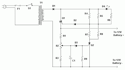
Build a Best Automatic 12V Lead Acid Battery Charger Circuit Diagram. This Best Automatic 12V Lead Acid Battery Charger Circuit Diagram will charge any 12V lead acid battery including flooded, gel and AGM. It is fully automatic and will charge at a rate up to about 4A until the battery voltage reaches a preset point at which it will switch to a very low current float charge.
If the battery voltage drops again the charger will begin charging until the voltage once again reaches the cut off point. In this way it can be left connected to a battery indefinitely to maintain full charge without causing damage. An LED indicates when the battery is fully charged. Sourced By Circuitsstream
Best Automatic 12V Lead Acid Battery Charger Circuit Diagram
Commponents
Notes | R1, R3 | 2 | 330 Ohm 1/4W Resistor | |
| R2 | 1 | 100 Ohm 1/4W Pot | |
| R4, R5, R7, R8 | 4 | 82 Ohm 2W Resistor | |
| R6 | 1 | 100 Ohm 1/4W Resistor | |
| R9 | 1 | 1K 1/4W Resistor | |
| C1 | 1 | 220uF 25V Electrolytic Capacitor | |
| D1 | 1 | P600 Diode | Any 50V 5A or greater rectifier diode |
| D2 | 1 | 1N4004 Diode | 1N4002, 1N4007 |
| D3 | 1 | 5.6V Zener Diode | |
| D4 | 1 | LED (Red, Green or Yellow) | |
| Q1 | 1 | BT136 TRIAC | |
| Q2 | 1 | BRX49 SCR | |
| T1 | 1 | 12V 4A Transformer | See Notes |
| F1 | 1 | 3A Fuse | |
| S1 | 1 | SPST Switch, 120VAC 5A | |
| MISC | 1 | Wire, Board, Heatsink For U1, Case, Binding Posts or Alligator Clips For Output, Fuse Holder |
R2 will have to be adjusted to set the proper finish charge voltage. Flooded and gel batteries are generally charged to 13.8V. If you are cycling the battery (AGM or gel) then 14.5V to 14.9V is generally recommended by battery manufacturers. To set up the charger, set the pot to midway, turn on the charger and then connect a battery to its output. Monitor the charge with a voltmeter until the battery reaches the proper end voltage and then adjust the pot until the LED glows steadily. The charger has now been set. To charge multiple battery types you can mount the pot on the front of the case and have each position marked for the appropriate voltage.
Q1 will need a heatsink. If the circuit is mounted in a case then a small fan might be necessary and can generally be powered right off the output of D1.
T1 is a transformer with a primary voltage appropriate to your location (120V, 220V, etc.) and a secondary around 12V. Using a higher voltage secondary (16V-18V) will allow you to charge 16V batteries sometimes used in racing applications.
If the circuit is powered off, the battery should be disconnected from its output otherwise the circuit will drain the battery slowly.
Q1 will need a heatsink. If the circuit is mounted in a case then a small fan might be necessary and can generally be powered right off the output of D1.
T1 is a transformer with a primary voltage appropriate to your location (120V, 220V, etc.) and a secondary around 12V. Using a higher voltage secondary (16V-18V) will allow you to charge 16V batteries sometimes used in racing applications.
If the circuit is powered off, the battery should be disconnected from its output otherwise the circuit will drain the battery slowly.

Friday, October 24, 2014
Automatic Range Switching Circuit Diagram
You can pick up a 3½-digit digital volt-meter module nowadays for a little as a couple quid. This is a simple and expensive way to fit out a piece of equipment with an instrument. Most modules are based on the well-known ICL7106 IC . They operate from an ordinary 9-V battery, and they only provide a fixed measuring range (200 mV or 2 V). The accessory circuit described here converts a DVM module into a voltmeter with 20-V and 200-V measuring ranges, with the added bonus of automatic range switching.
This requires a ground-referenced symmetrical supply voltage (±5 V) instead of a battery. An inexpensive TL431C is also used to generate an adjustable reference volt-age from the supply voltage. The circuit described here uses an LCD module with a fixed measuring range of 200 mV. It has three pins for driving the decimal point; two of them are used here.
Automatic Range Switching Schematic
This requires a ground-referenced symmetrical supply voltage (±5 V) instead of a battery. An inexpensive TL431C is also used to generate an adjustable reference volt-age from the supply voltage. The circuit described here uses an LCD module with a fixed measuring range of 200 mV. It has three pins for driving the decimal point; two of them are used here.
Automatic Range Switching Schematic

This is how the circuit works: IC1 converts the voltage to be measured by the DVM module into a ground-referenced voltage. This part of the circuit is based on a design idea from Carsten Weber [1] that was pub-lished in the June 2005 issue of Elektor Electronics.
If the input voltage is less than 20 V, the voltage divider formed by R1 and R4 reduces it by a factor of 100. Transistor T2 is cut off, so R3 has no effect on the division ratio. The voltage at the junction of voltage divider R8/R13 is 200 mV because the open-collector output of comparator IC2A is in the high-impedance state. If the input voltage rises above 20 V, IC2A changes state and the voltage at the junction of voltage divider R8/R13 drops to less than 20 mV. In response to this, the out-put of comparator IC2B goes high and T2 conducts. R3 is now connected in parallel with R4.
This yields a division factor of 1000 (200-V range). Of course, the larger division factor also causes the input voltage of IC2A to drop. To prevent this comparator from changing back to its previous state (which would cause the circuit to act like a sort of oscillator), the value of R10 must be chosen such that the voltage at the junction of voltage divider R8/R13 is less than 20 mV, as previously mentioned. The calculated value (with R10 in parallel with R13) is approximately 9.6 mV. In practice, the value is around 18 mV due to the resistance of the output transistor of the comparator.
This means that the circuit will switch back to the lower voltage range when the input voltage drops below approximately 18 V. The amount of hysteresis can be set by adjusting the value of R10. However, the circuit will oscillate if the value is too high. Film capacitors C1, C3 and C4 sup-press noise and create a certain amount of inertia for range switching. This prevents frequent back-and-forth switching in the threshold region.
The other two comparators of IC2 sup-ply mutually complementary output levels that depend on the measuring range. The associated decimal points of the DVM module are driven via p-channel FETs.The circuit has two trimpots: P1 is used to correct for the offset voltage of the operational amplifier (IC1), while P2 is used to set the threshold level for range switching For this purpose, first adjust the trimpot to produce the maximum possible reference voltage (around 3.4 V). Next apply an input voltage that causes a display reading of 19.99 (which ideally means 19.99 V). Now turn P2 until the measuring range switches.
As a check, reduce the input voltage to force the measuring range to switch back, and then slowly increase the input voltage again. The ideal setting is reached when the measuring range switches before the DVM module displays an ‘overrange’ indication. Link
Author : Rainer Reusch - Copyright: Elektor
Monday, October 20, 2014
Automatic Low Power Emergancy Light Circuit diagram
Here is a white-LED-based emergency light that offers the following advantages. 1-It is highly bright due to the use of white LEDs. 2-The light turns on automatically when mains supply fails, and turns off when mains power resumes. 3-It has its own battery charger. When the battery is fully charged, charging stops automatically. The charger power supply section is built around 3-terminal adjustable regulator IC LM317 (IC1), while the LED driver section is built around transistor BD140 (Q2).
In the charger power supply section, an input AC main is stepped down by T1 to deliver 9V, 500mA to the bridge rectifier, which comprises diodes D1 through D4. Filter capacitor C1 eliminates ripples. Unregulated DC voltage is fed to input pin 3 of IC1 and provides charging current through D5 and limiting resistor R15. By adjusting preset P1, the output voltage can be adjusted to deliver the required charging current. When the battery gets charged to 6.8V, D6 conducts and charging current from IC1 finds a path throughQT1 to ground and it stops charging of the battery. When mains power is available, the base of Q2 remains high and Q2 does not conduct. Thus LEDs are off.
On the other hand, when mains fails, the base of Q2 becomes low and it conducts. This makes all the LEDs glow. The mains power supply, when available, charges the battery and keeps the LEDs off as Q2 remains cut-off. During mains failure, the charging section stops working and the B1 supply makes the LEDs glow. Assemble the circuit on a general-purpose PCB and enclose in a cabinet with enough space for battery and switches. We have tested the circuit with twelve 10mm white LEDs. You can use more LEDs provided the total current consumption does not exceed 1.5A. Driver transistor Q2 can deliver up to 1.5A with proper heat-sink arrangement.
Circuit diagram:
In the charger power supply section, an input AC main is stepped down by T1 to deliver 9V, 500mA to the bridge rectifier, which comprises diodes D1 through D4. Filter capacitor C1 eliminates ripples. Unregulated DC voltage is fed to input pin 3 of IC1 and provides charging current through D5 and limiting resistor R15. By adjusting preset P1, the output voltage can be adjusted to deliver the required charging current. When the battery gets charged to 6.8V, D6 conducts and charging current from IC1 finds a path throughQT1 to ground and it stops charging of the battery. When mains power is available, the base of Q2 remains high and Q2 does not conduct. Thus LEDs are off.
On the other hand, when mains fails, the base of Q2 becomes low and it conducts. This makes all the LEDs glow. The mains power supply, when available, charges the battery and keeps the LEDs off as Q2 remains cut-off. During mains failure, the charging section stops working and the B1 supply makes the LEDs glow. Assemble the circuit on a general-purpose PCB and enclose in a cabinet with enough space for battery and switches. We have tested the circuit with twelve 10mm white LEDs. You can use more LEDs provided the total current consumption does not exceed 1.5A. Driver transistor Q2 can deliver up to 1.5A with proper heat-sink arrangement.
Circuit diagram:

Fully Automatic Emergency Light Circuit Diagram
Parts:
P1 = 2.2K
R1-R12 = 100R-1/2W
R13 = 1K-1/2W
R14 = 180R-1/2W
R15 = 16R/5W
R16 = 1.2K
C1 = 1000uF-25V
D1-D5 = 1N4007
D6 = 6.8V-0.5W Zener
D7-D18 = 10mm- White LEDs
Q1 = BC548
Q2 = BD140
B1 = 6V-4.5Ah Battery
IC1 = LM317
T1 = 9Vac-Transformer
P1 = 2.2K
R1-R12 = 100R-1/2W
R13 = 1K-1/2W
R14 = 180R-1/2W
R15 = 16R/5W
R16 = 1.2K
C1 = 1000uF-25V
D1-D5 = 1N4007
D6 = 6.8V-0.5W Zener
D7-D18 = 10mm- White LEDs
Q1 = BC548
Q2 = BD140
B1 = 6V-4.5Ah Battery
IC1 = LM317
T1 = 9Vac-Transformer
Sunday, September 14, 2014
Automatic Water Pump Controller Wiring diagram Schematic
Simple Automatic Water Pump Controller Circuit Diagram is a series of functions to control the Automatic Water Pump Controller Circuit in a reservoir or water storage. As the water level sensor made with a metal plate mounted on the reservoir or water tank, with a sensor in the short to create the top level and a detection sensor for detecting long again made the lower level and ground lines connected to the bottom of reservoirs or reservoir.
The series of automatic water pump controller is designed with 2 inputs NOR by 4 pieces and relay that is activated by the transistor. Automatic water pump schema requires +12 VDC voltage source and can be used to control the water pump is connected to AC power . Here is the complete series of pictures.
Automatic Water Pump Controller Circuit Diagram
working principle series of automatic water pump controller above is. At the time the water level is below both sensors, the output IC1C (pin 10) will be LOW, Kemudin when the water began to touch the lower level sensor, the output IC1C (pin10) remains LOW until the water touches the sensor level above, then the output IC1C (pin 10) going HIGH and active relay through Q1 and turn on the water pump to meguras reservoir.
At the muli down and water level sensors for water untouched MKA IC1C output (pin 10) remains HIGH until the new water untouched semuasensor IC1C output (pin 10) LOW and water pump died. The series of automatic water pump controller is equipped with SW1 which serves to reverse the logic of drains (the output of IC1C) and the concept of water supplied (output dri IC1D).
When SW1 is connected to IC1D the water pump will turn on when the water does not touch all the sensors and will die when all the sensors tesentuh water. Automatic water pump controller can be used to fill or drain the water according to which mode is selected via SW1.
List Component Automatic Water Pump Controller
R1 = 15K
R2 = 15K
R3 = 10K
R4 = 1K
D1 = LED
D2 = 1N4148
Q1 = BC337
IC1 = 4001
SW = SPDT Switches
Relay RL1 = 12V
Saturday, September 6, 2014
Automatic fan controller circuit
This schema will turn on/off 12V DC fan or CPU fan when temperature above normal temperature.You can set turn on temperature by adjust VR1. This schema use an NTC (Negative temperature coefficient)which is a thermistor is one in which the zero-power resistance decreases with an increase in temperature. So If temperature increate the voltage at pin 3 on LM311 will decreated .The resistance of NTC is about 10K at 25c.
VR1 should be multi-turn potentiometer type such 10K/25 turn
VR1 should be multi-turn potentiometer type such 10K/25 turn
Subscribe to:
Posts (Atom)
