Monday, November 3, 2014
Versatile Micropower Battery Protector
Main Features
- Disconnects load at preset battery voltage
- Automatically reconnects load when battery recharged
- Ultra-low power consumption (<20ma)
- Miniature size
- 10A maximum rating
- Suitable for use with 4.8-12.5V batteries
- Transient voltage protection (optional)
- Cars, boats & caravans
- Security systems
- Emergency lighting
- Small solar installations
- Camera battery packs
- Many other low-power applications

Back in May 2002, we (Silicon Chip) presented the "Battery Guardian", a project designed specifically for protecting 12V car batteries from over-discharge. This unit has proven to be very popular and is still available from kit suppliers. This new design does not supersede the Battery Guardian – at least not when it comes to 12V car batteries. Instead, it’s a more flexible alternative that can be used with a wide range of battery voltages.
In this new "Micropower Battery Protector", we’ve dispensed with the low-battery warning circuitry and the relatively cheap N-channel MOSFET used in the Battery Guardian in favour of a physically smaller module that steals much less battery power. It costs a little more but can switch lower voltages, allowing it to be used with 6V & 12V lead-acid batteries and 4-cell to 10-cell NiCd and NiMH battery packs.
Most battery-powered equipment provides no mechanism for disconnecting the batteries when they’re exhausted. Even when the voltage drops too low for normal operation, battery drain usually continues until all available energy is expended. This is particularly true of equipment designed to be powered from alkaline or carbon cells but retro-fitted with rechargeables.
Circuit diagram:
Another example is emergency lighting and security equipment designed to be float-charged from the mains. In an extended blackout period, the batteries can be completely drained and may not recover when the mains power is finally restored.

Saturday, November 1, 2014
9V Battery Replacement Power Supply Circuit Diagram
9V Battery Replacement Power Supply Circuit Diagram
For one, it has to prevent interference from, for example, the ignition system reaching the attached circuit. It is also preferable that the entire circuit fits in the 9-V battery compartment. This circuit meets these requirements quite successfully and the design has nonetheless remained fairly simple. In the schematic we can recognize a filter, followed by a voltage regulator and a voltage indicator. D1, which protects the circuit against reverse polarity, is followed by an LC and an RC filter (C3/L1/L2/C1/R1/C2). This filter excludes various disturbances from the motorcycle power system.
Moreover, the design with the 78L08 and D3 ensures that the voltage regulator is operating in the linear region. The nominal system voltage of 14 V can sometimes sag to about 12 V when heavy loads such as the lights are switched on. Although the circuit is obviously suitable for all kinds of applications, we would like to mention that it has been extensively tested on a Yamaha TRX850. These tests show that the converter functions very well and that the interference suppression is excellent.
Saturday, October 25, 2014
Best Automatic 12V Lead Acid Battery Charger Circuit Diagram
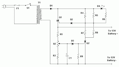
| R1, R3 | 2 | 330 Ohm 1/4W Resistor | |
| R2 | 1 | 100 Ohm 1/4W Pot | |
| R4, R5, R7, R8 | 4 | 82 Ohm 2W Resistor | |
| R6 | 1 | 100 Ohm 1/4W Resistor | |
| R9 | 1 | 1K 1/4W Resistor | |
| C1 | 1 | 220uF 25V Electrolytic Capacitor | |
| D1 | 1 | P600 Diode | Any 50V 5A or greater rectifier diode |
| D2 | 1 | 1N4004 Diode | 1N4002, 1N4007 |
| D3 | 1 | 5.6V Zener Diode | |
| D4 | 1 | LED (Red, Green or Yellow) | |
| Q1 | 1 | BT136 TRIAC | |
| Q2 | 1 | BRX49 SCR | |
| T1 | 1 | 12V 4A Transformer | See Notes |
| F1 | 1 | 3A Fuse | |
| S1 | 1 | SPST Switch, 120VAC 5A | |
| MISC | 1 | Wire, Board, Heatsink For U1, Case, Binding Posts or Alligator Clips For Output, Fuse Holder |
Q1 will need a heatsink. If the circuit is mounted in a case then a small fan might be necessary and can generally be powered right off the output of D1.
T1 is a transformer with a primary voltage appropriate to your location (120V, 220V, etc.) and a secondary around 12V. Using a higher voltage secondary (16V-18V) will allow you to charge 16V batteries sometimes used in racing applications.
If the circuit is powered off, the battery should be disconnected from its output otherwise the circuit will drain the battery slowly.
Thursday, October 23, 2014
Making a Solar Energy Powered an iPhone Battery Charger
For faster charging, a larger solar cell can be attached to the bag. Enough power can be generated to fully charge an iPhone in about 5.5 hours and an iPod Touch in 4 hours using a slightly larger solar cell with 6V at 250mAh. The charger will automatically switch to trickle charging when the cell reaches full charge. The charging current is limited to 100mA when charging using the mini USB port and the charging is limited to 280mA when charging using the barrel plug jack

.
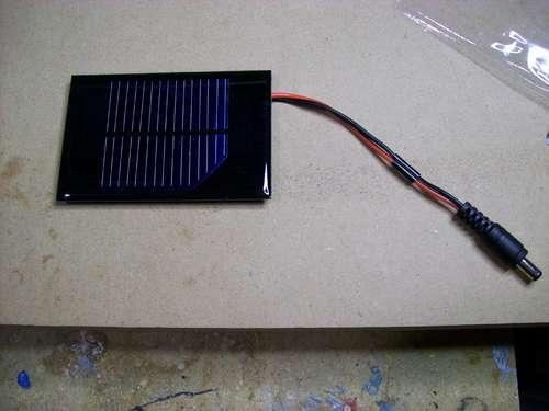
The materials needed to build the charger include a small solar cell, Lithium Polymer battery charger, minty boost kit, adhesive backed Velcro, Altoids tin, connector/wire, and small double adhesive squares as shown in the images below. An input power that ranges from 3.7V to 7V maximum can be accepted by the single cell Lithium Polymer. In bright sunlight, the solar cell maxes out at approximately 5V at 100mA. A larger solar cell with 6V at 250mA can be used for faster charging.

The images below show the assembly of minty boost kit where a JST connector is soldered to the minty boost PCB instead of connecting the battery holder in the kit. The minty boost circuit is allowed to connect to the Lithium Polymer battery charger circuit with this tiny connector. The minty boost is tested by connecting the battery pack and the charger circuit, the Lithium Polymer battery connects to the connector marked GND on the charger board and the minty boost connects to the connector marked SYS.

To fit the charger, a notch is cut out of the other side of the Altoids tin and used double sided adhesive to secure the charging circuit to the bottom of the Altoids as shown below. The bottom of either one of the circuit boards should not touch the bottom of the Altoids tin while reconnecting the minty boost PCB and the battery to the charging circuit.

Connecting or adding the solar cell can be done in different ways. Shortening the connector leads and plugging the barrel plug into the barrel jack on the charging circuit is one way. The other method is using another JST connector to replace the connector and plugging it into the third connector marked 5V on the charging circuit. Since there is no bog barrel plug sticking out of the side of the tin, using the second method is cleaner.
As shown in the photos below, some 2” Velcro was used to attach the solar cell to the top of the Altoids. To help protect the battery, a layer of clear packing tape was used for wrapping. N top of the two circuit boards, the battery pack is then set down. A red LED on the charger board will light up when the Mighty Minty Boost is set out in the bright sun. The iPod/iPhone/USB powered device can be connected once it is fully charged.
Monday, October 20, 2014
Battery Charger Circuit using Solar Cell Circuit Diagram

Friday, October 17, 2014
Designing A Li Ion Battery Charger with Load Sharing MCP73837

Thursday, October 16, 2014
USB Battery Charger Circuit Diagram

Low-Power Bus The low power bus powered functions derived all its power from the VBUS and must not draw over one unit load (100mA) according to the USB standard. It must even be able to work between the VBUS voltage of four.40V and five.25V.
Self-Power Self power functions can draw up to 100mA from the VBUS and the rest from its outside source. This is the most simplest to design.

Sunday, October 5, 2014
L200 Battery charger circuit
L200 Battery charger circuit
Notes.
- The circuit can be assembled on a good quality PCB or common board.
- The values of R2 & R3 can be obtained from the equation,
(R2//R3) =( V5-2)/(Io).
Where V5 is the charging voltage (voltage at pin 5) and Io is the charging current.
- The POT R8 can be used for fine adjustments of charging current.
- If battery is connected in reverse polarity the RED LED will glow.
- When the charging is going on the GREEN LED will glow.
- The rectified input voltage to the charger can be 18V.
Monday, September 22, 2014
Car Battery Charger description and circuit diagram
This charger will quickly and easily charge most any lead acid battery. The charger delivers full current until the current drawn by the battery falls to 150 mA. At this time, a lower voltage is applied to finish off and keep from over charging. When the battery is fully charged, the circuit switches off and lights a LED, telling you that the cycle has finished.
Circuit diagram
Parts
R1 500 Ohm 1/4 W Resistor
R2 3K 1/4 W Resistor
R3 1K 1/4 W Resistor
R4 15 Ohm 1/4 W Resistor
R5 230 Ohm 1/4 W Resistor
R6 15K 1/4 W Resistor
R7 0.2 Ohm 10 W Resistor
C1 0.1uF 25V Ceramic Capacitor
C2 1uF 25V Electrolytic Capacitor
C31000pF 25V Ceramic Capacitor
D1 1N457 Diode
Q1 2N2905 PNP Transistor
U1 LM350 Regulator
U2 LM301A Op Amp
S1Normally Open Push Button Switch
MISC Wire, Board, Heatsink For U1, Case, Binding Posts or Alligator Clips For Output
Notes
1. The circuit was meant to be powered by a power supply, which is why there is no transformer, rectifier, or filter capacitors on the schematic. There is no reason why you cannot add these.
2. A heatsink will be needed for U1.
3. To use the circuit, hook it up to a power supply/plug it in. Then, connect the battery to be charged to the output terminals. All you have to do now is push S1 (the "Start" switch), and wait for the circuit to finish.
4. If you want to use the charger without having to provide an external power supply, use the following circuit.

C1 6800uF 25V Electrolytic Capcitor
T1 3A 15V Transformer
BR1 5A 50V Bridge Rectifier 10A 50V Bridge Rectifier
S1 5A SPST Switch
F1 4A 250V Fuse
5. The first time you use the circuit, you should check up on it every once and a while to make sure that it is working properly and the battery is not being over charged.
Friday, September 19, 2014
Versatile Micropower Battery Protector
- Disconnects load at preset battery voltage
- Automatically reconnects load when battery recharged
- Ultra-low power consumption (<20ma)
- Miniature size
- 10A maximum rating
- Suitable for use with 4.8-12.5V batteries
- Transient voltage protection (optional)
- Cars, boats & caravans
- Security systems
- Emergency lighting
- Small solar installations
- Camera battery packs
- Many other low-power applications


Circuit diagram:

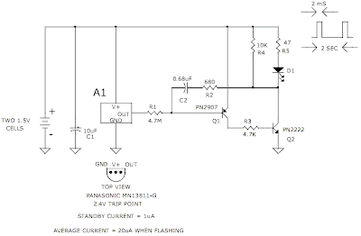
3v Low Battery Voltage Flasher
Thursday, September 18, 2014
Battery Equality Monitor

R1 = 2.K
R2 = 4.7K
R3 = 39K
R4 = 39K
R5 = 1.5K
R6 = 1.5K
Q1 = BC547
Q2 = BC547
Q3 = BC557
D1 = 3mm Red LED
D2 = 3mm GreenLED
B1 = DC 12 Volt
B2 = DC 12 Volt
Wednesday, September 17, 2014
USB powered battery charger circuit
Reliable Car Battery Tester
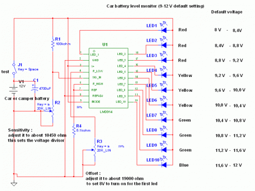
This solution is better than letting the internal voltage regulator set the 12V sample voltage to be feed into the internal voltage divider simply because it cannot regulate 12V when the voltage drops lower (linear regulators only step down). Simply wiring with no adjust, the regulator provides stable 1,25V which is fed into the precision internal resistor cascade to generate sample voltages for the internal comparators. Anyway the default setting let you to measure voltages between 8 and 12V but you can measure even from 0V to 12V setting the offset trimmer to 0 (but i think that under 9 volt your car would not start).
For the first comparator the voltage is : 0,833 V corresponding to 8 V
* * * * * voltage is : 0,875 V corresponding to 8,4 V
for the last comparator the voltage is : 1,25 V corresponding to 12 V
Have fun, learn and dont let you car battery discharge... ;-)
e-mail: jonathan.filippi@virgilio.it
Monday, September 15, 2014
Battery powered Night Lamp Circuit
Ultra-low current drawing 1.5V battery supply
An optional Photo resistor will switch-off the schema in daylight or when room lamps illuminate, allowing further current economy.
This device will run for about 3 months continuously on an ordinary AA sized cell or for around 6 months on an alkaline type cell but, adding the Photo resistor schemary, running time will be doubled or, very likely, triplicated.

R1,R2___________1M 1/4W Resistors
R3_____________47K 1/4W Resistor (optional: see Notes)
R4____________Photo resistor (any type, optional: see Notes)

C1____________100nF 63V Polyester Capacitor
C2____________220µF 25V Electrolytic Capacitor

D1______________LED Red 10mm. Ultra-bright (see Notes)
D2___________1N5819 40V 1A Schottky-barrier Diode (see Notes)

IC1____________7555 or TS555CN CMos Timer IC

B1_____________1.5V Battery (AA or AAA cell etc.)
- IC1 must be a CMos type: only these devices can safely operate at 1.5V supply or less.
- If you are not needing Photo resistor operation, omit R3 & R4 and connect pin 4 of IC1 to positive supply.
- Ordinary LEDs can be used, but light intensity will be poor.
- An ordinary 1N4148 type diode can be used instead of the 1N5819 Schottky-barrier type diode, but LED intensity will be reduced due to the higher voltage drop.
- Any Schottky-barrier type diode can be used in place of the 1N5819, e.g. the BAT46, rated @ 100V 150mA.
Sunday, September 14, 2014
Simple Battery Charger Vehicle Wiring diagram Schematic
Simple Battery Charger Vehicle Circuit Diagram
Parts:
Resistors
R1 = 0.32R
R2 = 8.2R Capacitors
C1 = x 10,000 uF 63V
D1 = 1N4004
D2 = 1N4004
D3 = 1N4004
Q1 = MJ1504
IC REG = 7815
BR1 = 1N4004x4
B1 = 12 Volt Battery
TR 20 volts AC
R1 and R2 are as high power resistor 2W, 3W, 5W or higher. Q1 and IC requires a heatsink good. If they are mounted on the same heatsink and will decrease the schema turns Q1 gets too hot.
Saturday, September 13, 2014
Battery Charger with Temeperature Sensor
Ni Cd Battery Charger 12 18V Wiring diagram Schematic
Ni-Cd Battery Charger 12-18V Circuit Diagram

Battery Charger with Temeperature Sensor
| Battery charger with temperature sensor schematic |
