Showing posts with label solar. Show all posts
Showing posts with label solar. Show all posts
Sunday, October 26, 2014
Solar Charger use IC LM317
At this point is a Solar Charger Circuit to is used to charge information Acid otherwise Ni-album batteries using the solar energy power. The circuit harvests solar energy to charge a 6 volt 4.5 Ah rechargeable battery in favor of various applications. The stallion has Voltage and Current supervision and terminated voltage restrict sour facilities.
Circuit uses a 12 volt solar panel and a changeable voltage supervisor IC LM 317. The solar panel consists of solar cells each one rated on 1.2 volts. 12 volt DC is presented from the panel to charge the battery. Charging current passes through D1 to the voltage watchdog IC LM 317. By adjusting its Adjust pin, output voltage and current can subsist regulated.
| Solar Charger use IC LM317 Schematic |
VR is placed amid the adjust pin and ground to provide an output voltage of 9 volts to the battery. Resistor R3 confine the charging current and diode D2 prevents discharge of current from the battery. Transistor T1 and Zener diode ZD conduct yourself having the status of a stop rotten switch at what time the battery is ample. Normally T1 is rancid and battery gets charging current.
After the terminal voltage of the battery rises over 6.8 volts, Zener conducts and provides station current to T1. It followed by turns on education the output of LM 317 to prevent charging. If you want to specific voltage / current output , you can replacing ZD on the circuit above.
Saturday, October 25, 2014
Build a Solar Garden Light Circuit Diagram
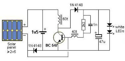
This is a Solar Garden Light Circuit Diagram that consists of a very simple system garden lighting that can be done by using some common electronic parts and a small solar panel. The electronic design is simple yet very efficient, has the advantage of being solar powered, it requires only one transistor, one 2.5 volt solar panel and some other common electronic components you can remove junk.
This solar lighting system automatically turns on the LEDs when the solar panel detects no light turns off when the solar panel produces more than 1v and charges the battery when the panel produces more than 2.1V
The coils in this circuit require a core material F29 and they must be made with wire of 0.095 mm in core 2.6x6mm. "This circuit uses the system joule thief (joule thief) to provide voltage necessary for the LED, so other coils can be tested.
The coils in this circuit require a core material F29 and they must be made with wire of 0.095 mm in core 2.6x6mm. "This circuit uses the system joule thief (joule thief) to provide voltage necessary for the LED, so other coils can be tested.
Solar Garden Light Circuit Diagram

Portable Solar Lantern
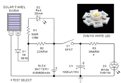
This portable solar lantern circuit uses 6 volt/5 watt solar panels are now widely available. With the help of such a photo-voltaic panel we can construct an economical, simple but efficient and truly portable solar lantern unit. Next important component required is a high power (1watt) white LED module.
When solar panel is well exposed to sunlight, about 9 volt dc available from the panel can be used to recharge a 4.8 volt /600 mAh rated Ni-Cd batterypack. Here red LED (D2) functions as a charging process indicator with the help of resistor R1. Resistor R2 regulates the charging current flow to near 150mA.
When solar panel is well exposed to sunlight, about 9 volt dc available from the panel can be used to recharge a 4.8 volt /600 mAh rated Ni-Cd batterypack. Here red LED (D2) functions as a charging process indicator with the help of resistor R1. Resistor R2 regulates the charging current flow to near 150mA.
Solar Lantern Circuit Schematic

Assuming a 4-5 hour sunlit day, the solar panel (150mA current set by the charge controller resistor R2) will pump about 600 – 750 mAh into the battery pack. When power switch S1 is turned on, dc supply from the Ni-Cd battery pack is extended to the white LED (D3). Resistor R3 determines the LED current. Capacitor C1 works as a buffer.
Note: After construction, slightly change the values of R1,R2 and R3 up/down by trial&error method, if necessary.
Note: After construction, slightly change the values of R1,R2 and R3 up/down by trial&error method, if necessary.
Source by :http://www.extremecircuits.net/2012/08/portable-solar-lantern.html
Thursday, October 23, 2014
Making a Solar Energy Powered an iPhone Battery Charger
The project was termed as Mighty Minty Boost as it was developed to function as iPod/iPhone charger with solar power. Aside from being small, it has a large battery capacity of 3.7V at 2000mAh and it accepts input power from 3.7V to 7V. As shown in the images below, it can become a compact USB power supply when the solar cell is removed after charging. The Velcro is used to secure the Mighty Minty Boost inside a backpack or messenger bag after unplugging the solar cell.
For faster charging, a larger solar cell can be attached to the bag. Enough power can be generated to fully charge an iPhone in about 5.5 hours and an iPod Touch in 4 hours using a slightly larger solar cell with 6V at 250mAh. The charger will automatically switch to trickle charging when the cell reaches full charge. The charging current is limited to 100mA when charging using the mini USB port and the charging is limited to 280mA when charging using the barrel plug jack

.
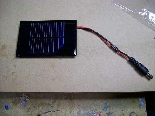
The materials needed to build the charger include a small solar cell, Lithium Polymer battery charger, minty boost kit, adhesive backed Velcro, Altoids tin, connector/wire, and small double adhesive squares as shown in the images below. An input power that ranges from 3.7V to 7V maximum can be accepted by the single cell Lithium Polymer. In bright sunlight, the solar cell maxes out at approximately 5V at 100mA. A larger solar cell with 6V at 250mA can be used for faster charging.

The images below show the assembly of minty boost kit where a JST connector is soldered to the minty boost PCB instead of connecting the battery holder in the kit. The minty boost circuit is allowed to connect to the Lithium Polymer battery charger circuit with this tiny connector. The minty boost is tested by connecting the battery pack and the charger circuit, the Lithium Polymer battery connects to the connector marked GND on the charger board and the minty boost connects to the connector marked SYS.

To fit the charger, a notch is cut out of the other side of the Altoids tin and used double sided adhesive to secure the charging circuit to the bottom of the Altoids as shown below. The bottom of either one of the circuit boards should not touch the bottom of the Altoids tin while reconnecting the minty boost PCB and the battery to the charging circuit.

Connecting or adding the solar cell can be done in different ways. Shortening the connector leads and plugging the barrel plug into the barrel jack on the charging circuit is one way. The other method is using another JST connector to replace the connector and plugging it into the third connector marked 5V on the charging circuit. Since there is no bog barrel plug sticking out of the side of the tin, using the second method is cleaner.
As shown in the photos below, some 2” Velcro was used to attach the solar cell to the top of the Altoids. To help protect the battery, a layer of clear packing tape was used for wrapping. N top of the two circuit boards, the battery pack is then set down. A red LED on the charger board will light up when the Mighty Minty Boost is set out in the bright sun. The iPod/iPhone/USB powered device can be connected once it is fully charged.

For faster charging, a larger solar cell can be attached to the bag. Enough power can be generated to fully charge an iPhone in about 5.5 hours and an iPod Touch in 4 hours using a slightly larger solar cell with 6V at 250mAh. The charger will automatically switch to trickle charging when the cell reaches full charge. The charging current is limited to 100mA when charging using the mini USB port and the charging is limited to 280mA when charging using the barrel plug jack

.
The materials needed to build the charger include a small solar cell, Lithium Polymer battery charger, minty boost kit, adhesive backed Velcro, Altoids tin, connector/wire, and small double adhesive squares as shown in the images below. An input power that ranges from 3.7V to 7V maximum can be accepted by the single cell Lithium Polymer. In bright sunlight, the solar cell maxes out at approximately 5V at 100mA. A larger solar cell with 6V at 250mA can be used for faster charging.

The images below show the assembly of minty boost kit where a JST connector is soldered to the minty boost PCB instead of connecting the battery holder in the kit. The minty boost circuit is allowed to connect to the Lithium Polymer battery charger circuit with this tiny connector. The minty boost is tested by connecting the battery pack and the charger circuit, the Lithium Polymer battery connects to the connector marked GND on the charger board and the minty boost connects to the connector marked SYS.

To fit the charger, a notch is cut out of the other side of the Altoids tin and used double sided adhesive to secure the charging circuit to the bottom of the Altoids as shown below. The bottom of either one of the circuit boards should not touch the bottom of the Altoids tin while reconnecting the minty boost PCB and the battery to the charging circuit.

Connecting or adding the solar cell can be done in different ways. Shortening the connector leads and plugging the barrel plug into the barrel jack on the charging circuit is one way. The other method is using another JST connector to replace the connector and plugging it into the third connector marked 5V on the charging circuit. Since there is no bog barrel plug sticking out of the side of the tin, using the second method is cleaner.
As shown in the photos below, some 2” Velcro was used to attach the solar cell to the top of the Altoids. To help protect the battery, a layer of clear packing tape was used for wrapping. N top of the two circuit boards, the battery pack is then set down. A red LED on the charger board will light up when the Mighty Minty Boost is set out in the bright sun. The iPod/iPhone/USB powered device can be connected once it is fully charged.

Monday, October 20, 2014
Battery Charger Circuit using Solar Cell Circuit Diagram
This is a circuit solar charger via USB cable emergency, it is an alternative circuit that uses solar cell and LM317 to regulate and make a recharge via USB for electronic equipment that can be IPODs, cell phones, MP3, tablets, etc..
The simplicity of the circuit can be noted that he does not have much appeal, but its enough to make a simple battery charge. The Solar Cell should be 12v current should be enough for loading, 10% of the batteries.
Battery Charger Circuit using Solar Cell Circuit Diagram

Subscribe to:
Posts (Atom)