Showing posts with label tester. Show all posts

Saturday, October 25, 2014

Universal Tester for 3 pin Devices

Most 3-terminal active components can be  tested statically using just an ohmmeter. But  when you have a lot of these devices to test,  the procedure soon becomes boring. That’s  where the idea came from to combine fast,  easy testing for these types of device into a  single instrument. 

The unit described here enables you to test  NPN and PNP bipolar transistors, N-or Pchannel FETs or MOSFETs, UJTs, triacs, and thyristors. Regardless of the type of device, the  tests are non-destructive. Universal connectors allow testing of all package types, including SMDs (up to a point). The unit lets you  change from one type of device to another in  a trice. It avoids using a multi-pole switch, as  they’re too expensive and hard to find. 
.
Circuit diagram :
Universal Tester for 3-pin Devices-Circuit Diagram
Universal Tester for 3-pin Devices Circuit Diagram
.
Here’s how to build a versatile instrument at  a ridiculously low cost. IC1 is a 4066 quad CMOS switch which will let us switch between bipolar transistors and FETs. LEDs D1–D4 tell us about the condition  of the test device, when we press the ‘Test’  button. The 4066 can only handle a few milliamps, not  enough for the other component types to be  tested, hence the reason for using relay RE1.  This 12 V relay offers two NO contacts. The  first applies power to the UJT test circuit, the  second applies it to the triac and thyristor test  circuit. 
.
Extensive testing has shown that the best way  to test UJT transistors is to do so dynamically,  with the help of a relaxation oscillator. Net-work R11/C1 sets the oscillator frequency to  around 2 Hz. On pin B1 of the UJT we find a  nice sawtooth, which is not of much interest  to us here. However, pin B2 gives good but  very short pulses. IC2, wired as a monostable,  lengthens these pulses so they can be clearly  seen via LED D5. 

The relay’s second pole is going to drive the  thyristor’ sortriac’s trigger pin. The value of  R18 is a good compromise with respect to the varying trigger currents for this type of  device. Resistor R17 is important, as the hold-ing current must be high enough for a triac;  250 mA is a good compromise. LED D6 tells  you if the device is in good condition or not;  but watch out, the test result must be con-firmed by briefly cutting the power in order  to reset the triac. 

On the web page for this article [1] you’ll find  the author’s CAD files (PCB layout and front  panel) along with some photos of his project.  On the prototype, the LEDs and the ‘Test’  button were wired onto the copper side of  the PCB. The six female connectors for the  devices being tested were salvaged, but there  are lots of models available on the market (the  pitch is standard). The test cable crocodile  clips must be as small as possible for testing  SMD devices.
Read More..

Monday, October 20, 2014

Audio Lm 3909 IC conduction tester

This tiny conductivity tester works with LM 3909. The tester makes a beeping sound if the resistance between the test probes between 0 and 100 O lies. Due to the volume of the beep, the resistance between the test probes can be determined.

Parts List

     R1 = 1 k
     C1 = 10 uF
     C2 = 100 nF
     LS = Loudspeaker 12 to 16 Ω
     IC1 = LM 3909
Read More..

Thursday, October 2, 2014

Simple Transistor Hfe Tester Circuit Diagram Using IC 741

  1. P1 is used to set a reference voltage derived from voltage UXY UD1 (or D2 for a PNP transistor). This means that l the setting of the potentiometer is directly proportional to the hpp; of the transistor under test and is independent of supply voltage.
  2. The voltage across R2 and the voltage set with P1 are compared by lC1 which is connected as a comparator. Potentiometer P1 is now set so that the LED at the output of the op-amp just lights or is just dimmed.
  3. This hfe tester is interesting because of its simplicity and because it enables the B of both PNP and NPN transistors to be measured.
  4. At this setting the voltage across the potentiometer is equal to the voltage across R2. Switch S1 is used to switch from NPN to PNP (or vice versa) by reversing the polarity of voltage UXY.
  5. LEDs D3 and D4 in the supply lines ensure that the input voltages to be measured are within the common mode range of the opamp used.
  6. Furthermore the measurement is independent of the supply voltage of the tester. As the diagram shows, the base current of the transistor under test travels via R1. Its base current IB is thus equal to The voltage drop across the collector resistor is hfe x IB x R2.
Read More..

Wednesday, September 17, 2014

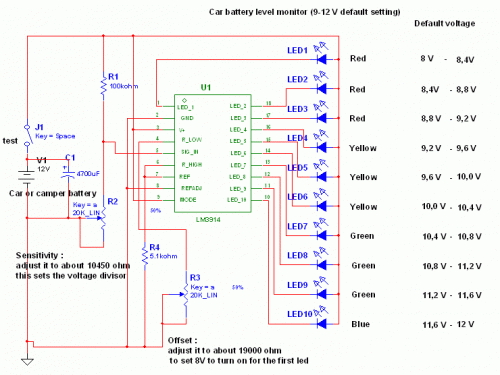
Reliable Car Battery Tester

www.streampowers.blogspot.com

This schema uses the popular and easy to find LM3914 IC. This IC is very simple to drive, needs no voltage regulators (it has a built in voltage regulator) and can be powered from almost every source. This schema is very easy to explain: When the test button is pressed, the Car battery voltage is feed into a high impedance voltage divider. His purpose is to divide 12V to 1,25V (or lower values to lower values).

This solution is better than letting the internal voltage regulator set the 12V sample voltage to be feed into the internal voltage divider simply because it cannot regulate 12V when the voltage drops lower (linear regulators only step down). Simply wiring with no adjust, the regulator provides stable 1,25V which is fed into the precision internal resistor cascade to generate sample voltages for the internal comparators. Anyway the default setting let you to measure voltages between 8 and 12V but you can measure even from 0V to 12V setting the offset trimmer to 0 (but i think that under 9 volt your car would not start).

There is a smoothing capacitor (4700uF 16V) it is used to adsorb EMF noise produced from the ignition coil if you are measuring the battery during the engine working. Diesel engines would not need it, but Im not sure. If you like more a point graph rather than a bar graph simply disconnect pin 9 on the IC (MODE) from power. The calculations are simple (default)

For the first comparator the voltage is : 0,833 V corresponding to 8 V
* * * * * voltage is : 0,875 V corresponding to 8,4 V
for the last comparator the voltage is : 1,25 V corresponding to 12 V
Have fun, learn and dont let you car battery discharge... ;-)
author: Jonathan Filippi
e-mail: jonathan.filippi@virgilio.it

Read More..