Showing posts with label how. Show all posts
Showing posts with label how. Show all posts
Thursday, October 23, 2014
How to Make your own Breadboard
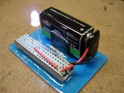
Often we do not have the opportunity or the money to keep our hobby, sometimes we lack tools, but always there is a knack for everything, is what we see here in this article was originally published at indestructible. He teaches you how to make your own breadboard using scrap old computers, in fact it uses sockets IDE cable. The breadboard makes life easier for those who like to create electronic circuits, and can only plug components without using solder.


Friday, September 12, 2014
How Regulator with 2 Photocoupler
Working of Regulator with 2 Photocoupler that is :
- Photocoupler N901 - used as a coupling-off control on the regulator by mikrokontrol. Which is set high and low voltage B + (st-by at the B + voltage is low). Control of the pin-37 POWER mikrokontrol → V610 → VD913 V908 → N901.
- Photocoupler N903 - used to control on-off the regulator of X-ray circuit protector. X-ray protector circuit of flyback → VD451 → VD452 → SCR VS472. If the flyback voltage regulator over the job will automatically be turned off by N903
- To disable the X-ray circuit protector, it can be temporarily removed photocoupler N903 first. In normal conditions the voltage at the transistor V474 should be zero.

| Regulator Schematics |
- Disable by removing the first circuit protectors N903
- Check the voltage of 300V
- Check all transistors
- Check the start voltage of 300V by R909 >> R906 to the base of transistor power regulator
- Check the feedback C910 >> R904 (to oscillate)
Thursday, September 11, 2014
How to create a simple adjusting volume for amplifier
This circuit usually used for amplifier that do not require additional device in one box amplifiers. Enhancements such as Equalizer , Tone Control , Mixer , etc. Only by requiring a potentiometer mono or stereo if stereo power amplifier , and few cables you can make this circuit easily.
See picture below :

First connect the cable from the power amplifier input to pin2 potentio , and connect ground to pin 1 , then connect the output of tuner or other media player to pin 3. Try turning to the right then the sound will be high , and if played left back then the sound will below.
Monday, September 8, 2014
How to fix a plug


# If you are an underage be careful when you work with AC.So always get the assistance from an elder
Friday, September 5, 2014
How to Dial in Your Cars Audio System
Level setting, done by ear, is more art than science. It can be done using an oscilloscope but since few people have one of those laying around well cover doing it by ear. Basically you want to start with the first component in the chain (the head unit) and work your way to the last component (the amplifier).
1. Start by turning all of the input level adjustment knobs (gain controls) on your components fully counter-clockwise (to their minimum setting). Set the tone controls (bass, treble, loudness) on your head unit to no boost (bass and treble level = 0 and loudness is off). If you have more than one RCA pair you will want to set each gain adjustment separately. Make sure your fader and balance controls are set to the channel you want to adjust first. This can be an individual channel if you have individual gain adjustments or a pair of channels if you have one gain for two channels.
2. Next set all of your equalizers settings (if you have an equalizer) to the center (detent) position so they produce no boost or cut. What we want is as pure a signal as possible.
3. Put in some good quality source material, preferably a CD with strong output and a clean recording. Hard rock would be a bad choice here. Try something cleaner, maybe acoustic, that youre familiar with.
4. Turn the decks volume up slowly until you begin to hear distortion. When you hear it, stop and back off slightly until you no longer hear it. If you dont hear distortion, even when the volume is all of the way up then you have a quality head unit. Thats what were looking for.
5. Now with your head unit at maximum undistorted volume move on to the next component. Adjust its input gain until you begin to hear distortion. Back off slightly.
6. Continue this process until you have all of the components in the chain at their maximum undistorted level.
7. When you reach the amplifiers you may need to wear earplugs to adjust them to their maximum level. As before, turn up the gain until you hear audible distortion. This should be audible even with earplugs in. But honestly, if you have to wear earplugs to listen the distortion level is probably not a factor :)
Thats it. Play some music and verify that everything sounds right. Congratulations! Youve just learned to properly adjust the settings on your car audio system.
Read More..
1. Start by turning all of the input level adjustment knobs (gain controls) on your components fully counter-clockwise (to their minimum setting). Set the tone controls (bass, treble, loudness) on your head unit to no boost (bass and treble level = 0 and loudness is off). If you have more than one RCA pair you will want to set each gain adjustment separately. Make sure your fader and balance controls are set to the channel you want to adjust first. This can be an individual channel if you have individual gain adjustments or a pair of channels if you have one gain for two channels.
2. Next set all of your equalizers settings (if you have an equalizer) to the center (detent) position so they produce no boost or cut. What we want is as pure a signal as possible.
3. Put in some good quality source material, preferably a CD with strong output and a clean recording. Hard rock would be a bad choice here. Try something cleaner, maybe acoustic, that youre familiar with.
4. Turn the decks volume up slowly until you begin to hear distortion. When you hear it, stop and back off slightly until you no longer hear it. If you dont hear distortion, even when the volume is all of the way up then you have a quality head unit. Thats what were looking for.
5. Now with your head unit at maximum undistorted volume move on to the next component. Adjust its input gain until you begin to hear distortion. Back off slightly.
6. Continue this process until you have all of the components in the chain at their maximum undistorted level.
7. When you reach the amplifiers you may need to wear earplugs to adjust them to their maximum level. As before, turn up the gain until you hear audible distortion. This should be audible even with earplugs in. But honestly, if you have to wear earplugs to listen the distortion level is probably not a factor :)
Thats it. Play some music and verify that everything sounds right. Congratulations! Youve just learned to properly adjust the settings on your car audio system.
Thursday, August 28, 2014
How to Build 1 2 30V 1 5A Variable Regulated Power supply Circuit
How to Build 1.2-30V/1.5A Variable Regulated Power supply, This is simple 1.2-30V/1.5A variable regulated power supply schema diagram The 110V-AC coming from the powercord is fed to the transformer TR1 via the on-off switch and the 500mA fuse. The 30vac output (approximately) from the transformer is presented to the BR1, the bridge-rectifier, and here rectified from AC (Alternating Current) to DC (Direct Current). If you dont want to spend the money for a Bridge Rectifier, you can easily use four general purpose 1N4004 diodes. The pulsating DC output is filtered via the 2200µF capacitor (to make it more manageable for the regulator) and fed to IN-put of the adjustable LM317 regulator (IC1). The output of this regulator is your adjustable voltage of 1.2 to 30volts varied via the Adj pin and the 5K potmeter P1. The large value of C1 makes for a good, low ripple output voltage.
1.2-30V/1.5A Variable Regulated Power supply Circuit Diagram
Why exactly 1.2V and not 0-volt? Very basic, the job of the regulator is two-fold; first, it compares the output voltage to an internal reference and controls the output voltage so that it remains constant, and second, it provides a method for adjusting the output voltage to the level you want by using a potentriometer. Internally the regulator uses a zener diode to provide a fixed reference voltage of 1.2 volt across the external resistor R2. (This resistor is usually around 240 ohms, but 220 ohms will work fine without any problems). Because of this the voltage at the output can never decrease below 1.2 volts, but as the potentiometer (P1) increases in resistance the voltage accross it, due to current from the regulator plus current from R2, its voltage increases. This increases the output voltage.
D1 is a general purpose 1N4001 diode, used as a feedback blocker. It steers any current that might be coming from the device under power around the regulator to prevent the regulator from being damaged. Such reverse currents usually occur when devices are powered down.
The ON Led will be lit via the 18K resistor R1. The current through the led will be between 12 - 20mA @ 2V depending on the type and color Led you are using. C2 is a 0.1µF (100nF) decoupler capacitor to filter out the transient noise which can be induced into the supply by stray magnetic fields. Under normal conditions this capacitor is only required if the regulator is far away from the filter cap, but I added it anyway. C3 improves transient response. This means that while the regulator may perform perfectly at DC and at low frequencies, (regulating the voltage regardless of the load current), at higher frequencies it may be less effective. Adding this 1 µF capacitor should improve the response at those frequencies.
R3 and the trimmer pot (P2) alows you to zero your meter to a set voltage. The meter is a 30Volt type with an internal resistance of 85 ohms. I you have or obtained a meter with a different Ri (internal resistance) you will have to adjust R3 to keep the current of meter to 1mA. Just another note in regards this meter, use the reading as a guideline. The reading may or may not be off by about 0.75volts at full scale, meaning if your meter indicates 30 volts it may be in reality almost 31 volts or 29 volts. If you need a more precies voltage, then use your multimeter.
Construction:
Because of the few components you can use a small case but use whatever you have available. I used a power cord from a computer and cut the computer end off. All computer power cords are three-prong. The ground wire, which is connected to the middle pin of the power plug is connected to the chassis. The color of the ground-wire is either green or green/yellow. It is there for your protection if the 110vac accidentally comes in contact with the supply housing (case). BE CAREFUL always to disconnect the powerplug when you working inside the chassis. If you choose to use an in-line, or clip-type fuseholder be sure to isolate it with heat shrink or something to minimize accidental touching.
I use perf-board (or Vero board) as a schema board. This stuff is widely available and comes relatively cheap. It is either made of some sort of fiber material or Phenolic or Bakelite pcb. They all work great. Some Phenolic boards come with copper tracks already on them which will make soldering the project together easier.
I mounted the LM317(T) regulator on a heatsink. If you use a metal/aluminum case you can mount it right to the metal case, insulated with the mica insulator and the nylon washer around the mounting screw. Note that the metal tab of the LM317 is connected internally to the Output pin. So it has to be insulated when mounting directly to the case. Use heat sink compound (comes in transparent or white color) on the metal tab and mica insulator to maximize proper heat transfer between LM317 and case/ or heatsink.
Drill the holes for the banana jacks, on/off switch, and LED and make the cut-out for the meter. It is best to mount everything in such a way that you are able to trouble-shoot your schema board with ease if needed. One more note about the on-off switch S1, this switch has 110VAC power to it. After soldering, insulate the bare spots with a bit of silicon gel. Works great and prevents electrical shock through accidental touching.
If all is well, and you are finished assembling and soldering everything, check all connections. Check capacitors C1 & C3 for proper polarity (especially for C1, polarity reversal may cause explosion). Hookup a multimeter to the power supply output jacks. Set the meter for DC volts. Switch on S1 (led will light, no smoke or sparks?) and watch the meter movement. Adjust the potentiometer until it reads on your multimeter 15Volts. Adjust trimpot P2 until the meter also reads 15volts. When done, note any discrepancies between your multimeter and the power supply meter at full scale (max output). Maybe there is none, maybe there is a little, but you will be aware of it. Good luck and have fun building!

Parts List
BR1 = Bridge Rectifier, 100V - 3A C1 = 2200 µF, 63V
IC1 = LM317, adjustable regulator C2 = 0.1 µF
V = Meter, 30V, Ri = 85 ohm C3 = 1µF, 40V
TR1 = Transformer, 25V, 2A Plug = 3-wire plug & cord
R1 = 18K, 5% S1 = On-Off toggle switch
R2 = 220 ohm, 5% D1 = 1N4001
R3 = 27K, 5% Fuse = 110V, 500mA, slow-blow
P1 = 5K, potentiometer FuseHolder, wire, solder, case, knob for P1
P2 = 10K, 10-turn trim-pot Red & Black Banana Jacks
Notes:
This is a simple, but low-ripple powersupply, and an excellent project if youre starting out in electronics. It will suit your needs for most of your bench testing and prototype applications. The output is adjustable from 1.2 volts to about 30 volts. Maximum current is about 1.5 amps which is also sufficient for most of your tinkering. It is relatively easy to build and can be pretty cheap if you have some or all the required parts. A printed schema board is not included and Im not planning on adding one since the whole thing can easily be build on perferated or vero board. Or buy one of Radio Shack/Tandys experimentors boards (#276-150). Suit yourself. The meter and the transformer are the money suckers, but if you can scrounge them up from somewhere it will reduce the cost significantly. BR1 is a full-wave bridge rectifier. The two ~ denotes AC and are connected to the 25vac output coming from the transformer. IC1 is a 3-pin, TO-220 model. Be sure to put a cooling rib on IC1, at its max 1.5 A current it quickly becomes very hot..
All the parts can be obtained from your local Radio Shack or Tandy store. The physical size of the power supply case depends largely on the size of the meter & transformer. But almost anything will do. Go wild.
Sourced By Tony van roon
Subscribe to:
Posts (Atom)
