Showing posts with label receiver. Show all posts
Showing posts with label receiver. Show all posts
Thursday, October 23, 2014
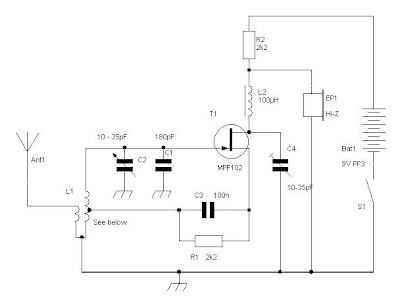
Simple Regenerative Receiver Circuit Diagram 80m or 40m
This is a simple design, can have excellent results, he is a recipient of regeneration, if you have never built any receiver, this is one you will build Easy. The circuit described is simple and has many limitations in sensitivity and selectivity, but is able to receive signals from radio amateurs (40m or 80m) in SSB and CW, and as output using a small headset crystal.
He will have a saturation if there are strong stations available on AM broadcast band of 41m at night.L1 is a small toroid T50-2 (red) with about 18 to 20 times (40m) or 35 to 40 times (80m) in the main winding connected to the FET with a single coupling circuit facing the antenna connection.
The center tap is about 20% of the primary winding. C1 is adjusted to set the radio band to the 40m and C2 then acts as a fine tuning within the band.The supply of 12 to 14V, R2 should be increased 5K6 or 6K8 output will be higher and similar sensitivity to-100dBm (about 2uV).
Regenerative Receiver Circuit Diagram

Sunday, September 14, 2014
AM Receiver
Description:
This is a compact three transistor, regenerative receiver with fixed feedback. It is similar in principle to the ZN414 radio IC which is now no longer available. The design is simple and sensitivity and selectivity of the receiver are good.
Circuit diagram
![Circuit]()
Notes:
All general purpose transistors should work in this schema, I used three BC109C transistors in my prototype.The tuned schema is designed for medium wave. I used a ferrite rod and tuning capacitor from an old radio which tuned from approximately 550 - 1600kHz. Q1 and Q2 form a compund transistor pair featuring high gain and very high input impedance. This is necessary so as not to unduly load the tank schema.
The 120k resistor provides regenerative feedback,between Q2 output and the tank schema input and its value affects the overall performance of the whole schema. Too much feedback and the schema will become unstable producing a "howling sound". Insufficient feedback and the receiver becomes "deaf". If the schema oscillates,then R1s value may be decreased; try 68k. If there is a lack of sensitivity, then try increasing R1 to around 150k. R1 could also be replaced by a fixed resisor say 33k and a preset resistor of 100k. This will give adjustment of sensitivity and selectivity of the receiver.
Transistor Q3 has a dual purpose; it performs demodulation of the RF carrier whilst at the same time, amplifying the audio signal. Audio level varies on the strength of the received station but I had typically 10-40 mV. This will directly drive high impedance headphones or can be fed into a suitable amplifier.
Construction:
All connections should be short, a veroboard or tagstrip layout are suitable. The tuning capacitor has fixed and moving plates. The moving plates should be connected to the "cold" end of the tank schema, this is the base of Q1, and the fixed plates to the "hot end" of the coil, the juction of R1 and C1. If connections on the capacitor are reversed, then moving your hand near the capacitor will cause unwanted stability and oscillation.
Finally here are some voltagee checks from my breadboard prototype.This should help in determining a working schema:-
All measurements made with a fresh 9volt battery and three BC109C transistors with respect to the battery negative terminal.
Parts
Q1 (b) 1.31V
Q2 (b) 0.71V
Q2 (c) 1.34V
Q3 (b) 0.62V
Q3 (c) 3.87V
This is a compact three transistor, regenerative receiver with fixed feedback. It is similar in principle to the ZN414 radio IC which is now no longer available. The design is simple and sensitivity and selectivity of the receiver are good.
Circuit diagram
Notes:
All general purpose transistors should work in this schema, I used three BC109C transistors in my prototype.The tuned schema is designed for medium wave. I used a ferrite rod and tuning capacitor from an old radio which tuned from approximately 550 - 1600kHz. Q1 and Q2 form a compund transistor pair featuring high gain and very high input impedance. This is necessary so as not to unduly load the tank schema.
The 120k resistor provides regenerative feedback,between Q2 output and the tank schema input and its value affects the overall performance of the whole schema. Too much feedback and the schema will become unstable producing a "howling sound". Insufficient feedback and the receiver becomes "deaf". If the schema oscillates,then R1s value may be decreased; try 68k. If there is a lack of sensitivity, then try increasing R1 to around 150k. R1 could also be replaced by a fixed resisor say 33k and a preset resistor of 100k. This will give adjustment of sensitivity and selectivity of the receiver.
Transistor Q3 has a dual purpose; it performs demodulation of the RF carrier whilst at the same time, amplifying the audio signal. Audio level varies on the strength of the received station but I had typically 10-40 mV. This will directly drive high impedance headphones or can be fed into a suitable amplifier.
Construction:
All connections should be short, a veroboard or tagstrip layout are suitable. The tuning capacitor has fixed and moving plates. The moving plates should be connected to the "cold" end of the tank schema, this is the base of Q1, and the fixed plates to the "hot end" of the coil, the juction of R1 and C1. If connections on the capacitor are reversed, then moving your hand near the capacitor will cause unwanted stability and oscillation.
Finally here are some voltagee checks from my breadboard prototype.This should help in determining a working schema:-
All measurements made with a fresh 9volt battery and three BC109C transistors with respect to the battery negative terminal.
Parts
Q1 (b) 1.31V
Q2 (b) 0.71V
Q2 (c) 1.34V
Q3 (b) 0.62V
Q3 (c) 3.87V
Tuesday, August 26, 2014
Simple IR transmitter and a receiver


# Use common audio transformer
# Build this schema on a PCB
# Be patient and tune carefully
# dont supply over 12V
Subscribe to:
Posts (Atom)
