Showing posts with label led. Show all posts
Showing posts with label led. Show all posts
Thursday, October 30, 2014
LED Audio Level Meter Circuit
This circuit uses two quad op-amps to form an eight LED audio level meter. The op-amp used in this particular circuit is the LM324. It is a popular IC and should be available from many parts stores.
 |
| LED audio level meter schematic |
The 1K resistors in the circuit are essential so that the LEDs turn on at different audio levels. There is no reason why you cant change these resistors, although anything above 5K may cause some of the LEDs to never switch on. This circuit is easily expandable with more op-amps, and is not limited to use with the LM324. Pretty much any op-amp will work as long as you look up the pinouts and make sure everything is properly connected.
The 33K resistor on the schematic is to keep the signal input to the circuit at a low level. It is unlikely you will find a 33K resistor, so the closest you can get should do. The value of this resistor may need to be changed, so it is best you breadboard this circuit before actually constructing it on PCB. The circuit in its current form will accept line level inputs from sources such as the aux out on a Hi-Fi, all though could be easily modified to accept speaker inputs.
The audio + is connected to the main positive rail, while the audio - is used for signal input. The 50k pot can be used to vary the sensitivity of the circuit.

Sunday, October 26, 2014
AA cell drive 5 LED display flashing Single
This the circuit or schematic diagram inexpensive LED flashlight (LED display) at 5 LED amounts that apply runs on a single aa cell battery 1.2V size AA cell and has a cluster of 5 LED. By it use transistor x2 very the circuit is the character switching regulator boost up voltage 1.2V DC from be 3V DC for apply to LED super bright 5 Pcs. usability circuit be this amounts just press SW1 only.
Friday, October 24, 2014
Strip LED Lamp
Strip LEDs are available in different colours powered by direct current (DC) source. These LEDs are available as surface mount devices with current limiting resistors. Usually there are 300 LEDs in a 5-metre strip. The strip can be cut into pieces so that the bits having three or four LEDs can be used with 12V DC source. The circuit given here uses the strip LEDs to make an automatic white LED lighting source. The circuit is powered by a capacitor power supply connected to AC mains. Capacitor C1 drops the 230V AC, which is further rectified by the bridge rectifier module and is made ripple-free by C2. Zener diode (ZD1) provides 12V DC to the comparator circuit.

Resistor R1 is important in the power supply as it provides discharge path to the voltage stored in capacitor C1 after the circuit is unplugged from mains. The automatic working of the circuit is based on the light-sensing property of the light-dependent resistor (LDR). Operational amplifier CA3140 (IC1) is used as a comparator with two potential dividers in its inverting and non-inverting inputs. LDR1 and resistor R3 form one potential divider that provides a variable voltage at the inverting input pin 2 of IC1. Second potential divider comprises resistors R4 and R5, which provide half of the supply voltage (6V) to the non-inverting pin 3 of IC1. The output of IC1 depends on voltage level at inverting input pin 2 of IC1 as explained below.
In daylight, LDR1 has low resistance and the voltage at inverting input (pin 2) of IC1 is more than that of non-inverting input (pin 3). This makes IC1 output low, which drives transistor T1 into cut-off condition and strip LEDs do not glow. However, at night the light incident on LDR1 is low and its resistance is high. The voltage at inverting input of the comparator decreases, making it lower than the voltage at non-inverting input. This makes IC1 output high. Transistor T1 goes into saturation, thus connecting cathodes of LEDs to ground. All the LEDs in the strip turn on and remain that way till morning.
Assemble the circuit on a general-purpose PCB and enclose it in a suitable shock-proof case. Strip LEDs are available in ribbon-shaped form. Use 5cm bits (two bits) having three LEDs each. The strip can be cut at supply-contact points. Strip LEDs are arranged on a flexible belt with double-sided adhesive on the back side, so it can be glued to any surface. Connect the LED strip in the circuit with correct polarity. EFY note. Since the circuit uses 230V AC, there is a risk of electrical shock. Do not touch or troubleshoot when the circuit is plugged in. Before connecting the circuit to the power supply section, test it using 12V DC from a battery or DC power supply.

Resistor R1 is important in the power supply as it provides discharge path to the voltage stored in capacitor C1 after the circuit is unplugged from mains. The automatic working of the circuit is based on the light-sensing property of the light-dependent resistor (LDR). Operational amplifier CA3140 (IC1) is used as a comparator with two potential dividers in its inverting and non-inverting inputs. LDR1 and resistor R3 form one potential divider that provides a variable voltage at the inverting input pin 2 of IC1. Second potential divider comprises resistors R4 and R5, which provide half of the supply voltage (6V) to the non-inverting pin 3 of IC1. The output of IC1 depends on voltage level at inverting input pin 2 of IC1 as explained below.
In daylight, LDR1 has low resistance and the voltage at inverting input (pin 2) of IC1 is more than that of non-inverting input (pin 3). This makes IC1 output low, which drives transistor T1 into cut-off condition and strip LEDs do not glow. However, at night the light incident on LDR1 is low and its resistance is high. The voltage at inverting input of the comparator decreases, making it lower than the voltage at non-inverting input. This makes IC1 output high. Transistor T1 goes into saturation, thus connecting cathodes of LEDs to ground. All the LEDs in the strip turn on and remain that way till morning.
Assemble the circuit on a general-purpose PCB and enclose it in a suitable shock-proof case. Strip LEDs are available in ribbon-shaped form. Use 5cm bits (two bits) having three LEDs each. The strip can be cut at supply-contact points. Strip LEDs are arranged on a flexible belt with double-sided adhesive on the back side, so it can be glued to any surface. Connect the LED strip in the circuit with correct polarity. EFY note. Since the circuit uses 230V AC, there is a risk of electrical shock. Do not touch or troubleshoot when the circuit is plugged in. Before connecting the circuit to the power supply section, test it using 12V DC from a battery or DC power supply.
Thursday, October 23, 2014
LED Flasher Circuit Using 555 Timer IC
This is a simple LED flasher project that uses a common 555 timer IC for its operation. It is configured as an astable mode which means that its output is a square wave oscillator. Two LEDs are connected to its output in such a way that when one LED is ON, the other LED will turn OFF.
It uses only 10 simple parts that are easily available at any electronic shops. Capacitor C2 charges exponentially through resistors R1, R2 and the resistance of the trimpot. When C2 has charged to about 2/3 VCC it stops charging and it discharges to about 1/3 VCC through R2 and the trimpot resistance via pin 7. This is the standard operation of a 555 timer. When a Vcc of 5 V to 15 V DC is applied to the circuit, the LED will start to flash.

The frequency of the flashing can be changed by varying the resistance of the potentiometer or trimpot. Parts List The parts list of the simple LED project is as shown below.

Wednesday, October 22, 2014
Rangkaian Lampu Led Berjalan
The 555 Astable generates a timer in support of this circuit, an oscillator giving a make even wave output by pin 3 which is counted by 4017 to assign a running light effect. Rangkaian Lampu Led Berjalan :
Read More..
 |
| Rangkaian Lampu Led Berjalan |
The decade counter-barrier CD4017 has 10 outputs, for all low to climax transition next to the control input, rising skirt, the counter advances single LED. in the same way as untaken one extensive ball the the foremost LED illumination again and it goes on. You can vary the respect of R2 100K Linear potentiometer to construct LEDs run fast or else slow on the uptake. The frequency of oscillation of astable 555 is known having the status of f = 1.44 / ((R4 + 2 * (R2 + R3)) * C3)
The 10 outputs come up with 10 sour LEDs. The current thru the LED is partial by R1, the current can be there calculated like this (9V - 1.6V) / 1K = 7.4mA this is inside 20mA which is the danger limit of the CMOS output. You lack it to be sharp wear and tear transistors pro each output.
The cap C1 is a filter and C2 is to prevent racket by the side of pin 5 influencing the output like it is a control voltage item.You can cascade or else attach many extra counters with the CO or else incorporate on show pin 12 of 4017. The pin 15 reset is reserved next to low in favor of as well as, on above what is usual it wish reset the counter but is not used fashionable this circuit.
Monday, October 20, 2014
Three Flashing LED Doorbells For The Hearing Impaired
When the push switch is operated - the buzzer will sound and the LEDs will begin to flash. For the hearing members of the household - the buzzer acts as a regular doorbell. It also re-assures the visitor that the doorbell is working.
When the push switch is released the buzzer will stop - but the LEDs will continue to flash. The length of time they will go on flashing is set by the values of R2 & C1. With the values shown in the diagram - the LEDs will flash for a further 30 seconds or so. If you make R2 a variable resistor, you can adjust the time period. If you want longer than 30 seconds - increase the value of C1 or R2.
When the push switch is released the buzzer will stop - but the LEDs will continue to flash. The length of time they will go on flashing is set by the values of R2 & C1. With the values shown in the diagram - the LEDs will flash for a further 30 seconds or so. If you make R2 a variable resistor, you can adjust the time period. If you want longer than 30 seconds - increase the value of C1 or R2.

The last circuit will flash up to two groups of 3 LEDs in tandem. This circuit will flash the two groups alternately. The alternate flashing creates the illusion of movement - and makes the display more eye-catching. Note that - although Ive drawn the two groups of LEDs side by side - the individual LEDs can be mounted in any pattern you like.

The main difference between this circuit and the last one - is the addition of the two transistor switches. The switches will each flash up to 15 groups of 3 LEDs. And - because they are getting power directly from the battery - the LEDs will glow at their full brilliance.

Tuesday, September 16, 2014
White LED Lamp
Nowadays you can buy white LEDs, which emit quite a bit of light. They are so bright that you shouldn’t look directly at them. They are still expensive, but that is bound to change. You can make a very good solid-state pocket torch using a few of these white LEDs. The simplest approach is naturally to use a separate series resistor for each LED, which has an operating voltage of around 3.5 V at 20 mA. Depending on the value of the supply voltage, quite a bit of power will be lost in the resistors. The converter shown here generates a voltage that is high enough to allow ten LEDs to be connected in series. In addition, this converter supplies a constant current instead of a constant voltage.
 |  |
 |  |
A resistor in series with the LEDs produces a voltage drop that depends on the current through the LEDs. This voltage is compared inside the IC to a 1.25-V reference value, and the current is held constant at 18.4 mA (1.25 V ÷ 68 Ω). The IC used here is one of a series of National Semiconductor ‘simple switchers’. The value of the inductor is not critical; it can vary by plus or minus 50 percent. The black Newport coil, 220 µH at 3.5 A (1422435), is a good choice. Almost any type of Schottky diode can also be used, as long as it can handle at least 1A at 50V. The zener diodes are not actually necessary, but they are added to protect the IC. If the LED chain is opened during experiments, the voltage can rise to a value that the IC will not appreciate.
Resistors:
R1 = 1kΩ2
R2 = 68Ω
Capacitors:
C1 = 100µF 16V radial
C2 = 680nF
C3 = 100µF 63V radial
Inductors:
L1 = 200µH 1A
Semiconductors:
D1 = Schottky diode type PBYR745 or equivalent
D2-D5 = zener diode 10V, 0.4W
D6-D15 = white LED
IC1 = LM2585T-ADJ (National Semiconductor)
Wednesday, September 10, 2014
LED Audio Level Meter Circuit
This circuit uses two quad op-amps to form an eight LED audio level meter. The op-amp used in this particular circuit is the LM324. It is a popular IC and should be available from many parts stores.
| LED audio level meter schematic |
The 1K resistors in the circuit are essential so that the LEDs turn on at different audio levels. There is no reason why you cant change these resistors, although anything above 5K may cause some of the LEDs to never switch on. This circuit is easily expandable with more op-amps, and is not limited to use with the LM324. Pretty much any op-amp will work as long as you look up the pinouts and make sure everything is properly connected.
The 33K resistor on the schematic is to keep the signal input to the circuit at a low level. It is unlikely you will find a 33K resistor, so the closest you can get should do. The value of this resistor may need to be changed, so it is best you breadboard this circuit before actually constructing it on PCB. The circuit in its current form will accept line level inputs from sources such as the aux out on a Hi-Fi, all though could be easily modified to accept speaker inputs.
The audio + is connected to the main positive rail, while the audio - is used for signal input. The 50k pot can be used to vary the sensitivity of the circuit.
Monday, September 8, 2014
LED multivibrator
This is a fantastic schema because lots of beginners select this one as their first schema. by using this one you can do lots of things that means you can make pulse generators even.Here two LEDs are blinking one by one.
This can be operated by using 3v battery
parts:-
* Q1 and Q2 = C828
*C1 and C2 = 100uf
*R1 and R4= 47k
*R2 and R3= 33k
*LED=2 co lour leds
Hear if you want to add more leds you can use D400 instead of C828 then you can add leds up to 12.
Difference between LCD and LED
Difference between LCD and LED :-
LCD is a liquid crystal display and LED is light emitting diode, both LCD and LED TVs or any other Lcds are Liquid crystal display.The basic technology in both of them is same as both type consist of two layers of polarized glass through which liquid crystal allows and blocks light, LED is basically a subset of LCD TVs.
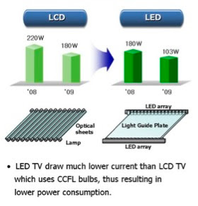
LED Lcds differ from the LCDs in such a way that in LCD fluorescent lights are used while in LEDs light emitting diodes are used, another thing is placement of light on Lcd, fluorescent lights in LCD are always behind the Lcd while light emitting diodes on LEDs are placed either on behind or on corners of the Lcd thats the reason LEDs TV are slimmer than the LCD TVs.
LED TVs provide better and clear picture because of two reasons first LED TVs work with wheel or distint RGB- colors to produce share colors and second, Light emitting diodes can be dimmer which helps in maintaining the colors and sharpness on picture.
LCD is a liquid crystal display and LED is light emitting diode, both LCD and LED TVs or any other Lcds are Liquid crystal display.The basic technology in both of them is same as both type consist of two layers of polarized glass through which liquid crystal allows and blocks light, LED is basically a subset of LCD TVs.
LED Lcds differ from the LCDs in such a way that in LCD fluorescent lights are used while in LEDs light emitting diodes are used, another thing is placement of light on Lcd, fluorescent lights in LCD are always behind the Lcd while light emitting diodes on LEDs are placed either on behind or on corners of the Lcd thats the reason LEDs TV are slimmer than the LCD TVs.
LED TVs provide better and clear picture because of two reasons first LED TVs work with wheel or distint RGB- colors to produce share colors and second, Light emitting diodes can be dimmer which helps in maintaining the colors and sharpness on picture.
Friday, September 5, 2014
LED Power Meter
LED power Meter circuit is a simple RF detector using diodes to charge a capacitor. The voltage developed across the capacitor is indicated by a multimeter set to a low voltage range. The circuit is soldered together without the need for a PC board, as can be seen in the diagram below and paper clips are used for the positive and negative terminals of the multimeter.
The level power output of an FM transmitter is indicated by the illumination of a LED and the voltage reading on the multimeter gives a further indication of the output.
A digital multimeter may be used but the presence of RF may produce a false reading. Likewise, the radiated energy may upset some analogue meters and you may get full scale deflection on the 15v range as well as the 250v range! But the LED wont lie. It will accurately indicate the RF and you can see the change in brightness as you adjust the coils in the output stage. Some of the cheapest and simplest multimeters will give the best results as they have a low sensitivity and the radiated RF energy will not induce a reading. Even a damaged multimeter can be used, provided the 10v or 15v DC scale is operating.
The reading is not calibrated and does not represent milliwatts output. It is only a visual indication.
We have designed over 10 FM transmitters for inclusion in the pages of this e-magazine and each one has different features and characteristics. Some are designed for 3v operation, some are for 9v operation, some are stable for hand-held situations and others are designed for high output. The illumination of the LED will range from barely visible to very bright.
LED Power Meter Parts
1 - 470R
1 - 100p ceramic
1 - 100n ceramic
2 - 1N 4148 diodes
1 - 5mm Red LED
1 - 2in (5cm) hook-up wire
2 - paper clips
No PC board required
Monday, September 1, 2014
Build a 3 Channels LED Flasher Wiring diagram Schematic
Build a 3 Channels LED Flasher Circuit Diagram. Inserting two 1-MO resistors, R1 and R2, in the output stage of one of the schema`s inverters limits the current needed by the oscillator tone more than a few pA. This schema includes a CD4007 package, which has three CMOS inverters. It forms a standard three-inverter oscillator. Resistors R1 and R2, in series with separate drains on inverter pins 8 and 13, limit the oscillator`s supply current. Capacitor C1 and resistors R5 set the off time of the oscillator, C1; R6 sets the on time.
Three Years LED Flasher Circuit Diagram
A VN10KM small-power FET, current limited by R4, drives two HLMP-3300 LEDs. The LEDs consume about 20 mA for 1 ms. Their average current determines battery life. Since the LEDs in the schema flash at 1 Hz, the average current drain is about 1/1000 of 20 mA, or 20 p.A. A 9-V battery should last about three years at the current drain-essentially the shelf life of an alkaline battery.
3V LED Chaser Wiring diagram Schematic
There are many 9V chaser diagram that seem to waste about 7V when driving LEDs that are only about 2V. This project is unique, because it uses only two inexpensive alkaline battery cells totaling 3V for power. Since most of the waste is eliminated, the cells last a long time.
Unlike the other diagram, this one flashes the LEDs for only about 30ms each, further extending the battery life. For user convenience, it has a stepper speed control and a brightness control. At slower speeds and with reduced brightness, the battery life is further extended considerably. Mounted in a circle, the LEDs appear to rotate as they step from one to the next. Link
Specifications
• Battery: Two alkaline cells (AA size were used in the prototype)
• Battery Life: AA cells C cells D cells
Minimum speed and brightness 8 months 2 years 4.9 years
Medium speed and brightness 6 months 1.5 years 3.6 years
Maximum speed and brightness 2 weeks 1.5 months 3.6 months
• Stepper speed: 2 LEDs/sec to 2 revolutions/sec
• Brightness: Controlled with Pulse Width Modulation, from very dim to 161mcd (very bright)
• Pulse Width Modulation frequency: 1.4KHz very bright to 6KHz very dim
• LED current: 15mA pulses, reduced to 10.5mA at maximum Pulse Width Modulation
• LED voltage drop: 1.76V (measured, not rated) @ 10.5mA
• Minimum battery voltage (total of both cells): <1.24V, schema is running but LEDs are not lit
1.6V, LEDs are very dim at maximum brightness
2.0V, LEDs reach almost full brightness, battery replacement is recommended.
• Radio interference: None
Circuit Description
The 74HC Cmos ICs are rated for a 2V to 6V power supply for high-speed logic diagram. They continue to operate at a much lower voltage but no longer meet high-speed logic specifications. To reach high speeds, their output current can momentarily exceed 400mA (low voltage drop) but thermal considerations limit maximum continuous output current to 20mA. Perfect for driving LEDs!
• IC2 is a 10 stage Johnson counter/decoder. On the rising edge of each clock pulse its outputs step one-at-a-time. It drives the anode of each conducting LED toward the positive supply.
• IC1a is a standard Cmos inverter Schmitt-trigger oscillator with C3 and C4 totaling 800nF for a very slow step rate. R2 is the speed control pot with R1 limiting its maximum speed. It clocks IC2 and feeds the inverters/drivers. D1 and R3 reduce its output high time to 30mS.
• IC1d, IC1e, IC1f and IC1b are paralleled inverter/drivers for a low output voltage drop and drive the emitter of T1 to ground.
• IC1c is another standard Cmos inverter Schmitt-trigger oscillator. R5 is its Pulse Width Modulation control and with D3 performs dimming of the LEDs. D2 and R4 extend the PWM’s maximum pulse width.
• T1 is a transistor that is used as a PWM switch. R7 limits maximum LED pulse current.
• C1 bypasses the battery’s supply voltage at low frequencies and C2 bypasses at high frequencies.
Construction
The ten LEDs mount on a Compact-Disc which is glued to a plastic box with contact cement. The box houses the Veroboard schema in its lower main part with the battery holder in its lid. Multiconductor ribbon cable joins the LEDs to the schema. The pots mount on the sides of the box.
Parts List
• Battery: Two alkaline cells (AA size were used in the prototype)
• Battery Life: AA cells C cells D cells
Minimum speed and brightness 8 months 2 years 4.9 years
Medium speed and brightness 6 months 1.5 years 3.6 years
Maximum speed and brightness 2 weeks 1.5 months 3.6 months
• Stepper speed: 2 LEDs/sec to 2 revolutions/sec
• Brightness: Controlled with Pulse Width Modulation, from very dim to 161mcd (very bright)
• Pulse Width Modulation frequency: 1.4KHz very bright to 6KHz very dim
• LED current: 15mA pulses, reduced to 10.5mA at maximum Pulse Width Modulation
• LED voltage drop: 1.76V (measured, not rated) @ 10.5mA
• Minimum battery voltage (total of both cells): <1.24V, schema is running but LEDs are not lit
1.6V, LEDs are very dim at maximum brightness
2.0V, LEDs reach almost full brightness, battery replacement is recommended.
• Radio interference: None
Circuit Description
The 74HC Cmos ICs are rated for a 2V to 6V power supply for high-speed logic diagram. They continue to operate at a much lower voltage but no longer meet high-speed logic specifications. To reach high speeds, their output current can momentarily exceed 400mA (low voltage drop) but thermal considerations limit maximum continuous output current to 20mA. Perfect for driving LEDs!
• IC2 is a 10 stage Johnson counter/decoder. On the rising edge of each clock pulse its outputs step one-at-a-time. It drives the anode of each conducting LED toward the positive supply.
• IC1a is a standard Cmos inverter Schmitt-trigger oscillator with C3 and C4 totaling 800nF for a very slow step rate. R2 is the speed control pot with R1 limiting its maximum speed. It clocks IC2 and feeds the inverters/drivers. D1 and R3 reduce its output high time to 30mS.
• IC1d, IC1e, IC1f and IC1b are paralleled inverter/drivers for a low output voltage drop and drive the emitter of T1 to ground.
• IC1c is another standard Cmos inverter Schmitt-trigger oscillator. R5 is its Pulse Width Modulation control and with D3 performs dimming of the LEDs. D2 and R4 extend the PWM’s maximum pulse width.
• T1 is a transistor that is used as a PWM switch. R7 limits maximum LED pulse current.
• C1 bypasses the battery’s supply voltage at low frequencies and C2 bypasses at high frequencies.
Construction
The ten LEDs mount on a Compact-Disc which is glued to a plastic box with contact cement. The box houses the Veroboard schema in its lower main part with the battery holder in its lid. Multiconductor ribbon cable joins the LEDs to the schema. The pots mount on the sides of the box.
Parts List
| 1 IC1 CD74HC14N or SN74HC14N | High-speed Cmos, Schmitt-trigger hex inverters |
| 1 IC2 CD74HC4017N or SN74HC4017N | High-speed Cmos, decade counter-decoder |
| 1 T1 2N3904 or 2N4401 | NPN transistor |
| 10 LEDs MV8191 High brightness | wide angle red LED (less than 2V) |
| 3 D1 to D3 1N4148 or 1N914 | Silicon diode |
| 2 R1, R3 100K 1/4W | resistor |
| 1 R2 1M Linear | taper potentiometer (speed) |
| 1 R4 330K 1/4W | resistor |
| 1 R5 1M Audio | taper (logarithmic) potentiometer (brightness) |
| 1 R6 680 1/4W | resistor |
| 1 R7 22 1/4W | resistor |
| 1 C1 100uF/10V or 100uF/16V | Electrolytic capacitor |
| 1 C2 0.1uF/50V or 0.1uF/100V | Ceramic disc capacitor |
| 1 C3 330nF/63V | Metalized poly capacitor |
| 1 C4 470nF/63V | Metalized poly capacitor |
| 1 C5 1nF/100V | Metalized poly capacitor |
| 2 misc.Alkaline battery cells | 1 misc. Plastic box |
| 1 misc.Battery holder | 3 misc. Vinyl feet for box |
| 1 misc. Compact Disc | 2 misc. Knobs for potentiometers |
| 1 misc. Hole plug for the CD’s center hole | 1 misc. 9 to 11 conductor ribbon cable |
1) The ICs are manufactured by Texas Instruments, and others.
2) The LEDs are manufactured by Fairchild Semiconductor.
3) Above manufacturers offer free samples.
Photos


Sunday, August 31, 2014
LED Circuit with Timer 555
This circuit LED reproduces the first LED sequence at this time used by FISA on behalf of Formula single racing. It may perhaps be alive used with slot car sets (such for example HO shin up AFX/Life Like/Tyco sets) or else means of communication controlled cars. IC1, a 555 timer IC, is used as a watch pulse generator. Its output is fed via NAND gates IC2a and IC2c to IC3, a 4024 binary counter. IC2b inverts the O4 output of 4024 binary counter IC3. originally, IC3 is reset and all its outputs are low, together with O4, which causes IC2b to present-day a rational climax to the pin 8 input of IC2c which after that passes pulses from the 555 timer circuit to the clock input of the 4024. IC3 then begins together with.
Following the count has reached binary 1111, the subsequently pulse sends the O4 output of IC3 high, which disables IC2c and IC3 stops with. The four used outputs of IC3 are connected to a resistor ‘ladder’ which acts to the same degree a clear-cut digital to analog convert-er (DAC). As the count increases so does the voltage produced by the side of the top of the ladder and this is connected to the inverting inputs of four comparators inside IC4 (an LM339) and to IC5, which is a 741 op amp furthermore connected while a comparator.
The categorical inputs of the comparators are connected to the taps of a voltage dividing wall, with the drumming voltages settle on using VR1, a 100kO trimpot. As IC3 counts, the rising stepped voltage from the DAC ladder switches the comparators on clothed in sequence, preliminary with IC4d and working up to IC5. in the same way as both comparator is curved on, its pair off of LEDs is lit; former LEDs 1 & 2, next LEDs 3 & 4 and so on. as soon as all five pairs of LEDs are lit, the then pulse from IC1 moves the binary count of IC3 to 10000, so the DAC voltage drops back to zilch and all LEDs are extinguished. by the same spell, with too stops, for the reason that the area of high pressure on O4 causes IC2c to check extra gate pulses. The circuit in that case remains reserve until the counter is reset by urgent pushbutton switch S1. This allows a recent sequence to initiate.
Thursday, August 28, 2014
LED Flasher Circuit Using 555 Timer IC
This is a simple LED flasher project that uses a common 555 timer IC for its operation. It is configured as an astable mode which means that its output is a square wave oscillator. Two LEDs are connected to its output in such a way that when one LED is ON, the other LED will turn OFF.
It uses only 10 simple parts that are easily available at any electronic shops. Capacitor C2 charges exponentially through resistors R1, R2 and the resistance of the trimpot. When C2 has charged to about 2/3 VCC it stops charging and it discharges to about 1/3 VCC through R2 and the trimpot resistance via pin 7. This is the standard operation of a 555 timer. When a Vcc of 5 V to 15 V DC is applied to the circuit, the LED will start to flash.
The frequency of the flashing can be changed by varying the resistance of the potentiometer or trimpot.Parts List The parts list of the simple LED project is as shown below.

Subscribe to:
Posts (Atom)
